Nodes – Pick & Drop Application Example
This flow contains the localization and navigation nodes that appeared in the Autonomous Navigation flow which was described in Autonomous Navigation Nodes. This pick and drop flow also has various additional nodes that define the pick and drop behavior of the robot, as described below.
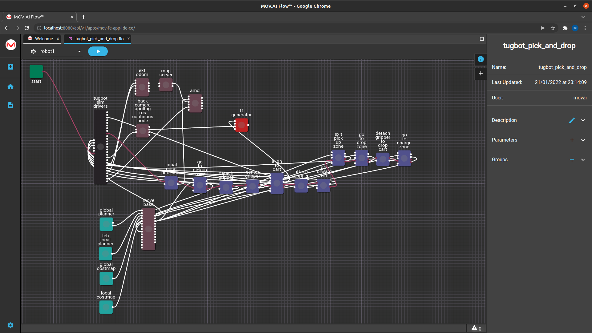
Go To Pickup Zone Node
The go to pickup zone node instructs the robot to go to pickup zone node. This is the area in where a cart has been left (by a human or something out of scope of this demo) to be picked up by the robot.

Click on it and expand the Parameters area of the right pane to display the parameters that can be configured to define the destination to which the robot will travel.
For example, the x_position and Y_ position parameters , as shown below –
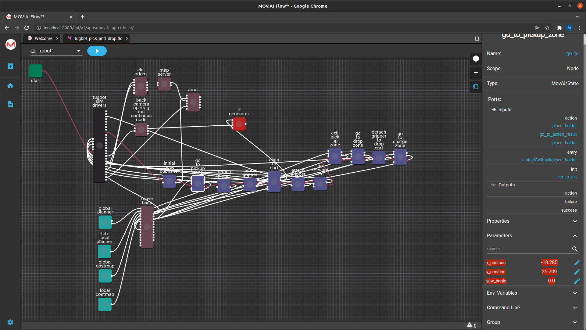
This position is in the pickup zone approximately where the cart is waiting.
This node instructs the robot to back up to where the court is waiting so that its back camera can see the April tag. According to the value of the yaw angle parameter
detach gripper
The detach gripper node has a Boolean value that sends a command to open (True) the gripper.

This value can be set to True or False, as shown below –
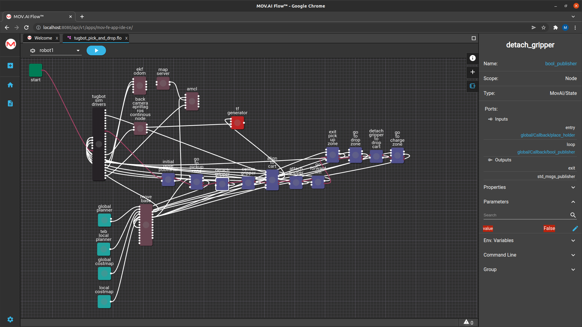
The output port of this node is attached to an input port on the tugbot sim drivers node that connects to the gripper controller that will give the command to the robot to open or close its gripper.
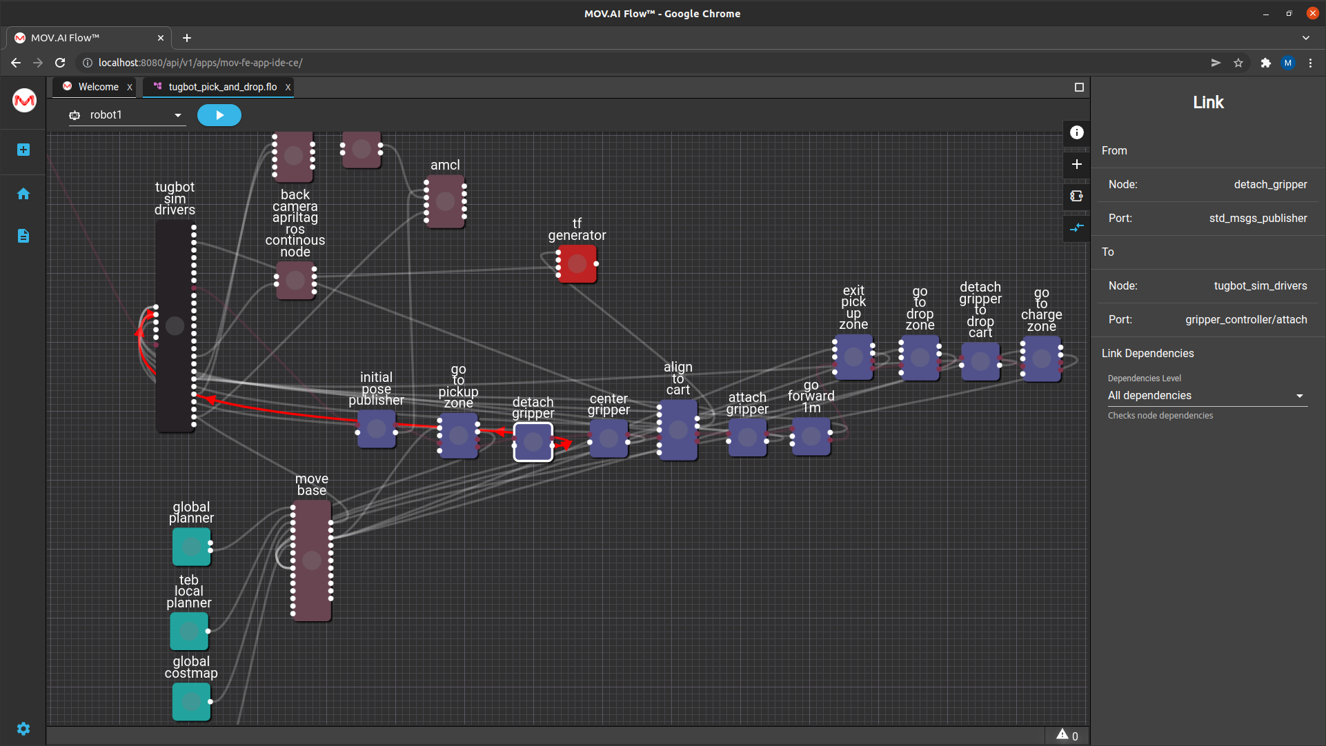
Note – The type of this node is bool_publisher.
Center Gripper

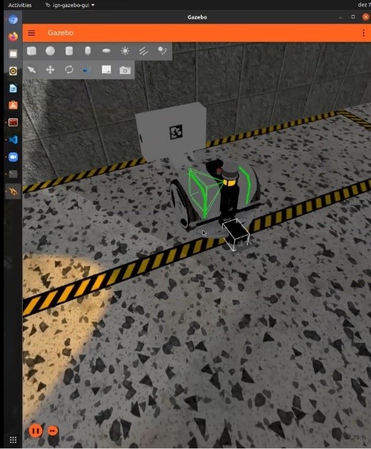
The center gripper of the Tugbot robot is attached to the end of a mechanical arm that can move right and left (horizontal to the ground).
The center gripper node is responsible for moving the gripper arm to the middle of the back of the robot, as shown below –
align to cart

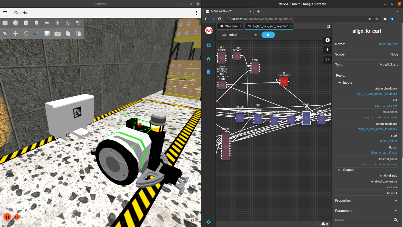
After the nodes described above have brought the robot to the cart, the align to cart node is ready to activate. This is a sophisticated node that performs a variety of functions, including –
- Scanning for the April tag
- Positioning the back of the robot directly in front of the April tag so that the gripper is a specific distance from the metal bar that it can grab
back camera AprilTag ROS continuous node

This is a standard ROS node that can detect an image of an April tag and determine its position so that it can be used in the flow.
tf generator

The alignment of the robot with the cart is actually a two-stage process. The tf_generator node creates a TF to which the robot can align its position along three axes.
Note – The initial TF is generated using the apriltag_ros node (with a QR code tag placed on the cart) and a projected TF is generated using the TF_gen_node as a middleman of the alignment process, which uses the robot’s odometry. The starting point is P1, the robot rotates so that the chosen camera (as specified by the parameter named camera) points to the front of the tag that has been generated by the Tf_gen node.
These three axes indicate the location of the April tag to which the robot must align itself, defined by the parameters of the tf generator node, as shown below –
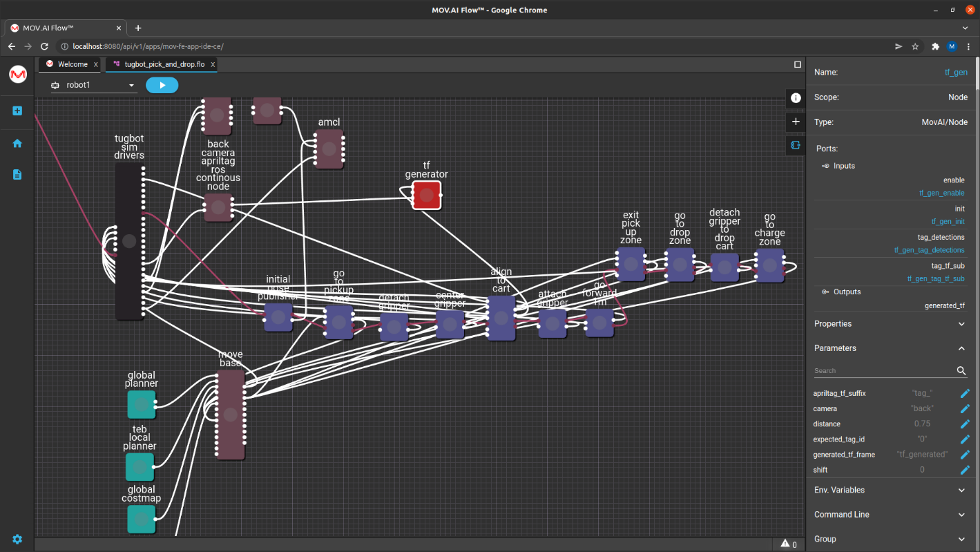
For example, the distance parameter indicates how far away the robot must position itself. This gives it something to which to align before the robot’s gripper tries to grab the cart.
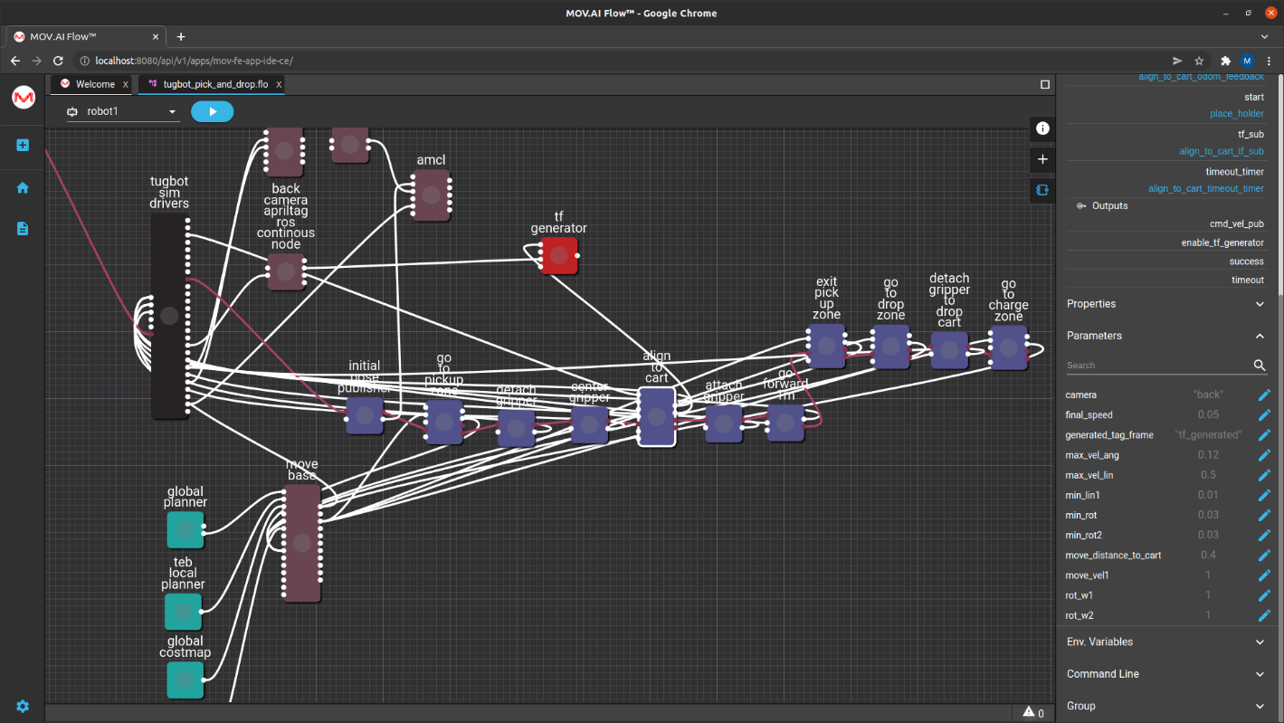
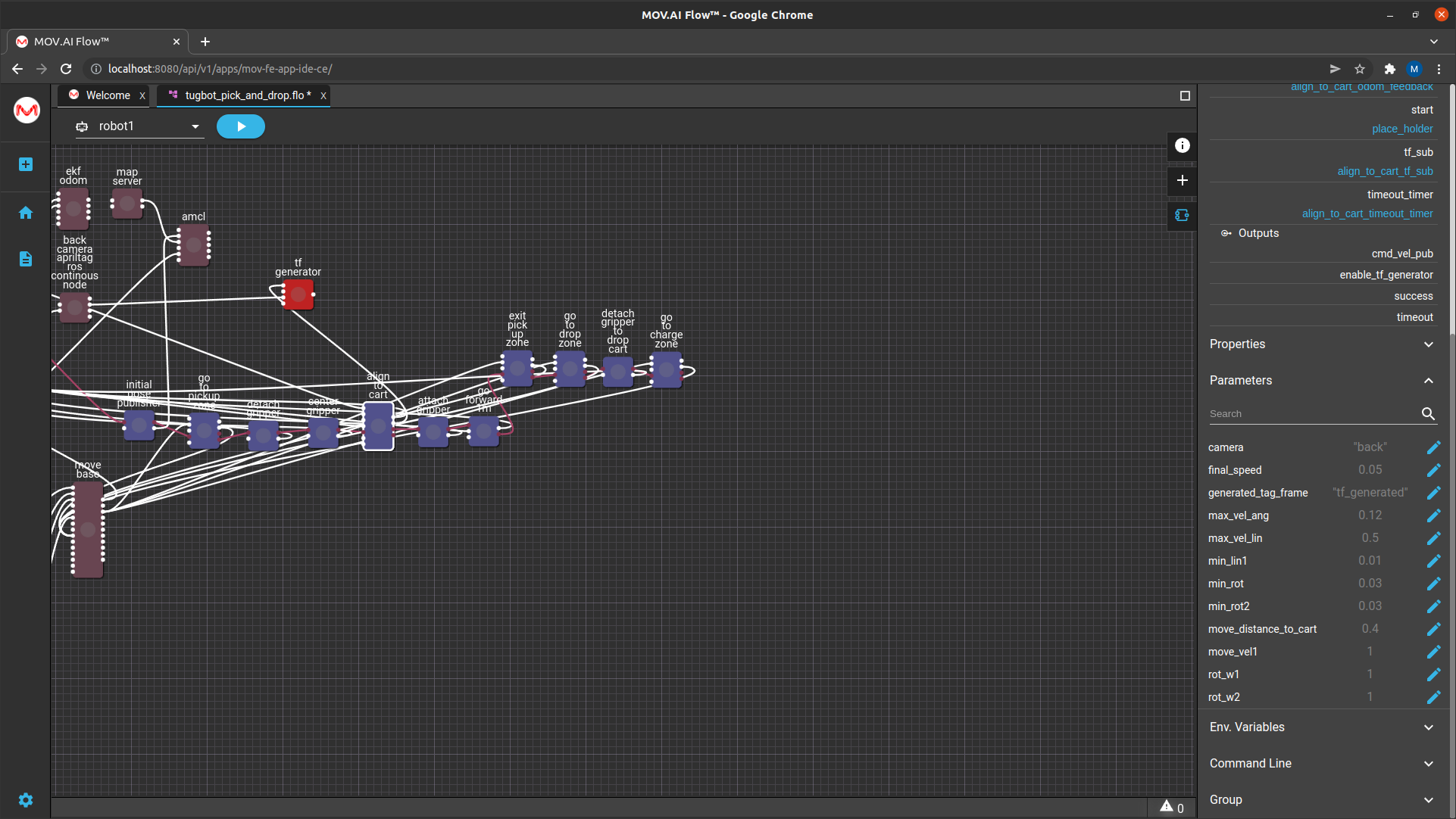
Click on the align cart node and expand the Parameters section to display its numerous parameters, such as the velocity (move_vel1) and rotation (min_rot) of the robot during alignment process, as shown below –
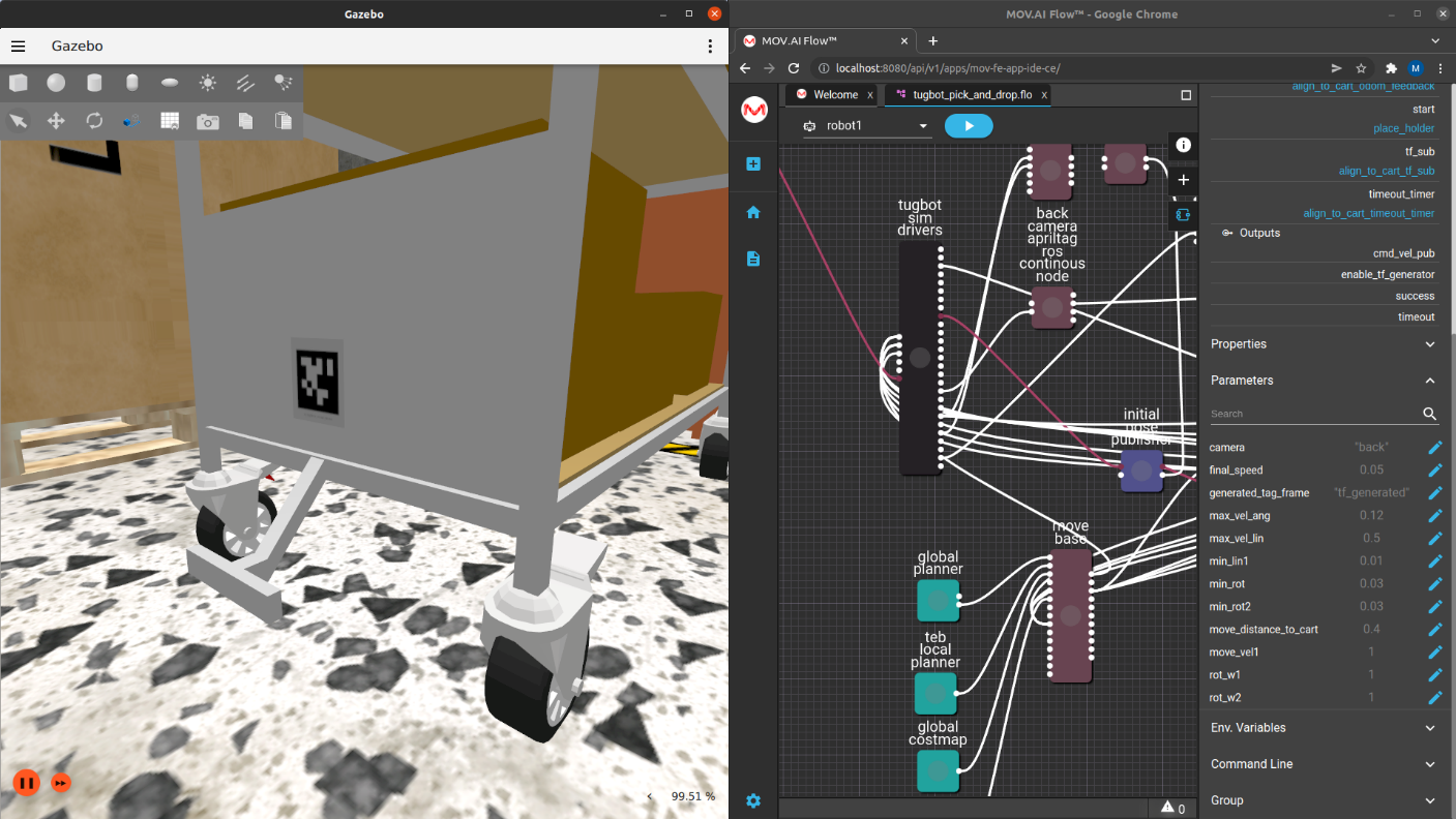
The robot stops so that its gripper is positioned on the bar near the bottom of the cart, as shown below –
attach gripper
The attach gripper node has a Boolean value that sends a command to close (True) its gripper.

This value can be set to True or False, as shown below –
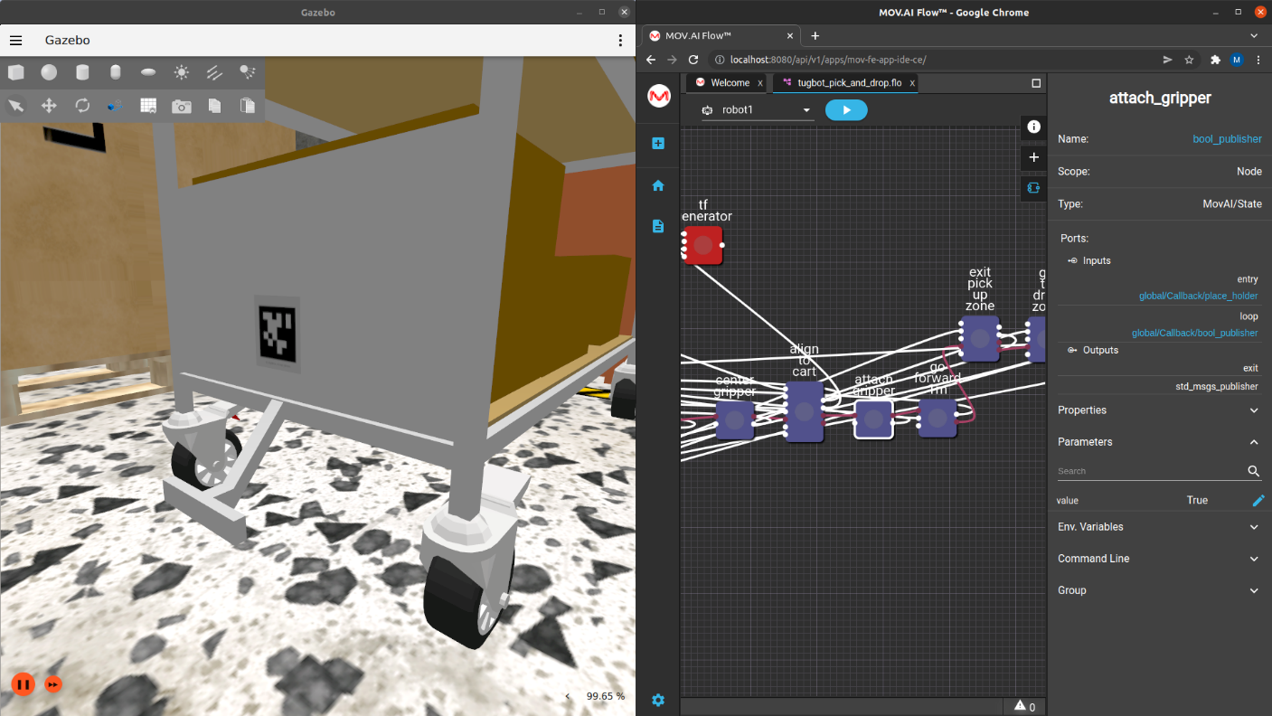
The output port of this node is attached to an input port on the tugbot sim drivers node that connects to the gripper controller that sends the command to the robot to open or close its gripper.
go forward 1 m

The go forward 1 m node moves the robot forward 1m, while it is gripping and pulling the cart with it.
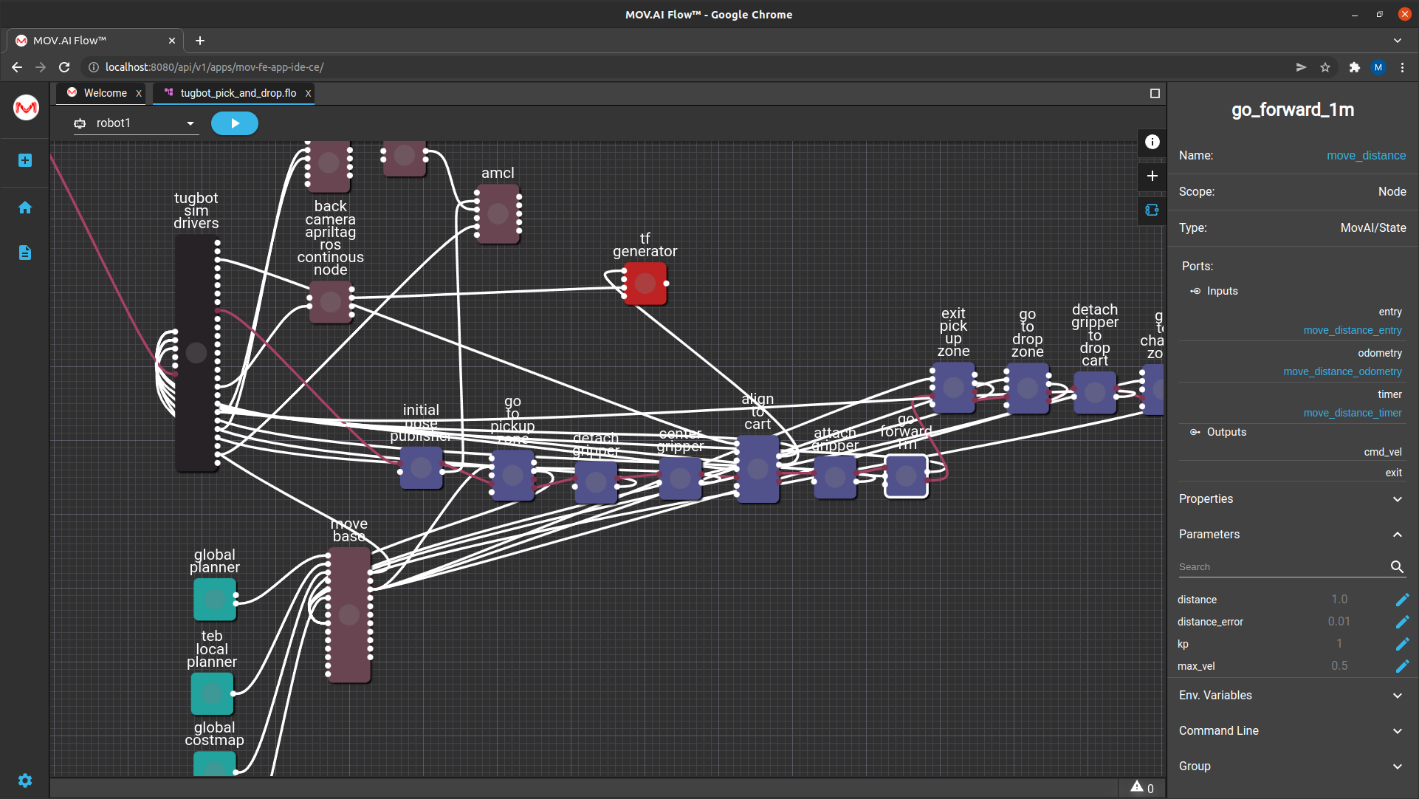
Note – This is the place where you should place your code that will check the sensor of the gripper in order to verify that the robot grabbed the cart; and if it has not grabbed the cart, your code must handle this situation by backing up the cart, realigning it and then grabbing the cart again. Alternatively, you can analyze the image of the robot’s back camera in order to verify that the cart is being pulled along with it.
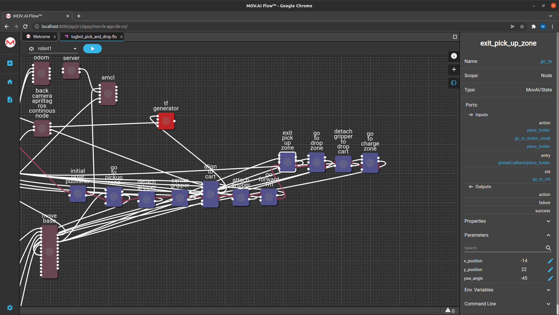
exit pick up zone
The exit pick up zone node is another go to node that instructs the robot to exit the pickup zone and travel to a midway point on the way to the drop off point, as shown below –

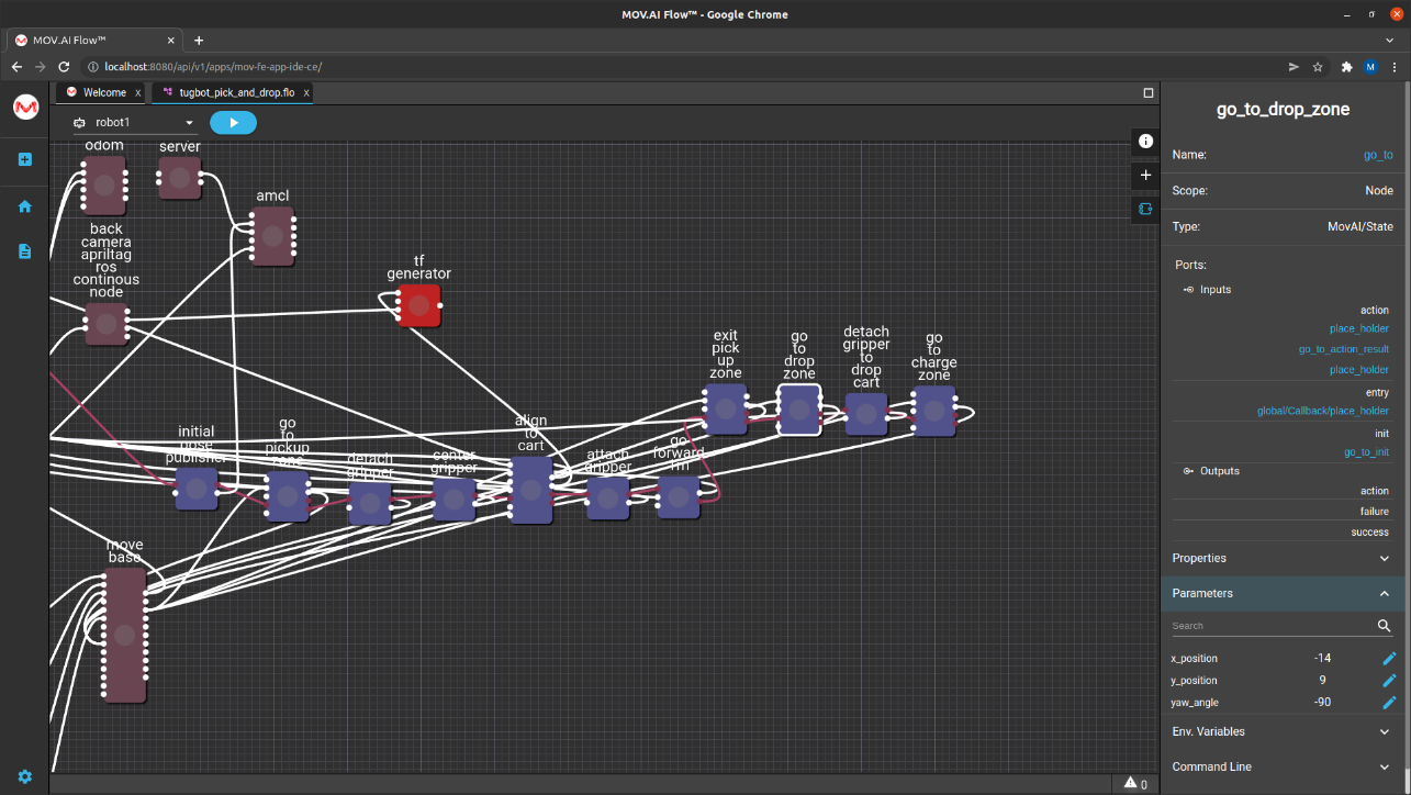
go to drop zone

The go to drop zone node is another go to node that instructs the robot to travel to the drop off zone.
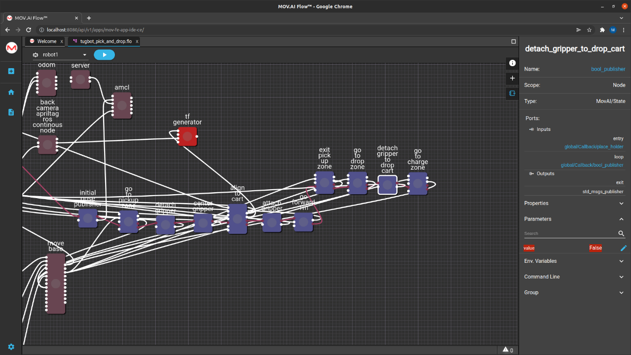
detach gripper to drop cart

The detach gripper to drop cart node has a False value so that it releases the cart in the drop off zone, as shown below –
go to charge zone

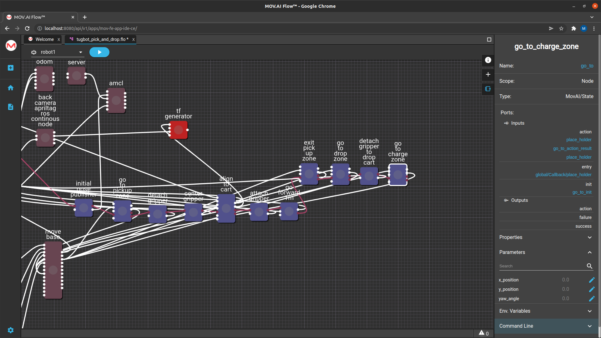
The go to charge zone node is another go to node that sends the robot to its initial position in the charging zone. Therefore, the x_position = 0, y_postion = 0 and the yaw_angle = 0.
You can use the April tag in the charge zone to align the cart to its docking station so that it can dock and charge itself. To do so, you can copy the align to cart node and modified it slightly in order to define this behavior.
For example, the align to cart node provides a parameter that enables you to specify which Camera to use. When picking up a cart, you might want the robot to use its back camera, but when docking in the charging station, you might want to use the robot’s front camera. The following shows the camera parameter of the align to cart node –
Note – Note that the charging station does not give feedback to indicate whether the robot has been properly docked and able to charge.
Updated 8 months ago
