One Model
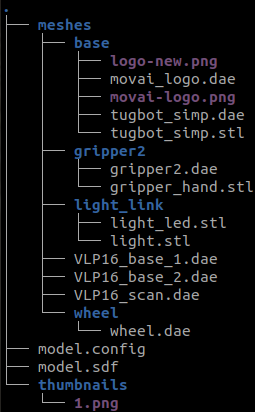
The following is the structure within the / my_modelsfolder.
There is a folder per Model. Each model -can be a static object or a robot - has a sdf file, a config file and a couple of folders with resources used by the model such as textures and meshes.
robot_name
This is the subfolder that contains all the folders and files that are required to define a specific robot or model. Rename this folder with the name of your robot.
Each of these are described in the sections below.
-
robot_name
-
model.config
-
model.sdf,
-
meshes,
- mesh.dae or mesh.obj
-
materials,
-
textures
- texture_image.png
-
-
thumbnails
- image.png
-
-
my_world_scene.sdf
Example: For the tugbot model - available at https://app.gazebosim.org/MovAi/fuel/models/Tugbot - we can identify these files inside the Tugbot folder:
model.config
This simple mandatory XML file contains general information about the robot asset that you are creating. The following shows an example model.config file for a Tugbot robot –
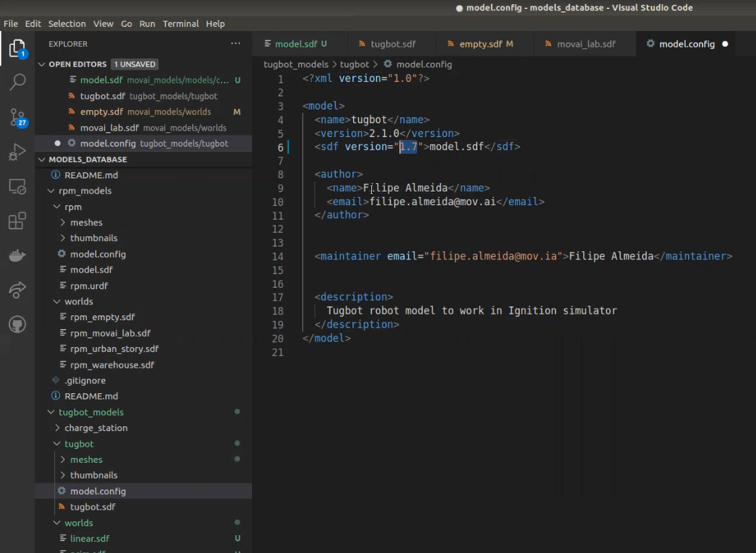
Note – An asterisk * indicates mandatory properties.
-
Name* – Specify a free text name for the robot model. It is important to specify the name of the robot’s SDF file here, such as model.sdf or tugbot.sdf, as described in model.sdf.
-
Version* – Specify any free text version for this robot model and its SDF file for your information purposes only.
-
sdf version* – Specify the SDF format version according to which you are building this file. Versions 1.7 and below are supported. You may refer to http://sdformat.org/spec for the details of SDFormat versions.

-
author – Specify the name and email address of the author. This is free text.
-
description – Specify any metadata information to describe this robot. This information will not appear anywhere else.
When importing a new model at Gazebo using the Resource Spawner menu, you will find a list of objects which name is read from the respective .config files.
model.sdf (Robot Description file)
This complex mandatory file contains a rich variety of parameters that enable Gazebo Fortress to simulate the robot and its environment ( worldand scene). This file describes the robot (its joints and links), the robot’s controllers to which MOV.AI can send commands in Gazebo Fortress, and the sensors from which MOV.AI can receive data from the simulated robot in Gazebo Fortress.
One of the great things about MOV.AI is that it provides the SDF file that enables immediate integration with Gazebo Fortress for the robots that it supports, such as the Tugbot and Husky robot.
Here’s how to do it yourself for any other robot.
In this case, you must define the robot’s model.sdf file yourself, as described in this section. You can use the tugbot.sdf file provided by MOV.AI as the basis if you want.
The document you're reading now walks you through creating this file.
In addition, you may refer to http://sdformat.org/spec?ver=1.7&elem=model for a description of how to define a model in the SDF file.

A tab of information is provided for each type of data structure that you can define, such as Model, Link, Joint, Sensor and so on.
All the world/scene/environment definitions go into a separate file named my_world_scene.sdfwhich is described in my_world_scene.sdf.
Defining the Physicality of a Robot in the SDF File
The following is an example of a robot and how its components can be defined in an SDF file. This example shows a robotic arm that has a base, two joints and three links.

Note – In addition, to the detailed descriptions in this topic, you may refer to Gazebo Fortress’s short example at <<<https://ignitionrobotics.org/docs/fortress/building_robot>>>.
Defining a Robot’s Links
A link of a robot is a physical segment of a robot’s body that connects between joints (described later in this topic). A link has a variety of properties, such as inertia, collisions (which defines the physical dimension and shape of the link) and visual appearance (which defines how this link appears in the simulation).

<link_type=”link”>
…
</link
See http://sdformat.org/spec?ver=1.7&elem=link for detailed information.
What is a Collision?
A collision is part of the definition of a link in a robot, as described above. The simulation executes physical computations in order to determine the collisions that might affect each part of a robot’s body (link), such as whether its movement might be restricted because of other robot components or objects in the scene.
Each component of a robot is represented in the simulation by a relatively simple shape, even though the simulator may show a more attractive complex version of this shape. This simple shape is called the collision. The simulation will only compute the physics of this collision representation of a link. Therefore, for example, a Panda robot may have a visually attractive representation of the robot, which shows each part of a lifelike representation of the robot in minute detail, as shown below –


However, because this detailed shape is so complex, the simulator uses a simpler geometric textual representation of each part, such as shown below, which makes it easier f to compute the physics of this robot’s movement.

Defining a Robot’s Joints

<joint_type=”revolute” names=my_joint”>
…
</joint
A joint represents a movable joint (also called an axis) of a robot’s body that causes relative motion between adjacent links. A joint has a variety of kinetic and dynamic properties, as well as a default position. Therefore, the definition of a joint in the SDF file specifies the two links that it connects, as well as its type. For instance, whether it’s a hinge joint that rotates on a single access and how far it can rotate on the axis; or whether it is a sliding joint that slides along an axis within a limited range specified by upper and lower limits and so on. The definition of a joint, does not specify any visual characteristics or a collision. Its definition only consists of the attributes described in the Joints tab of the SDFormat page. See http://sdformat.org/spec?ver=1.7&elem=joint for detailed information.

Defining the Robot’s Sensors
A sensor can send the information that it detects from the simulated robot in Gazebo Fortress to MOV.AI, such as a LiDAR sensor or camera. It is important to properly define the technical properties of each sensor according to the real technical specifications of that sensor so that the simulator can properly replicate its behavior.
MOV.AI currently supports the following sensors –
- Cameras – RGB, Depth, RGB+D
- IMU
- Lidar – 2D or 3D
At MOV.AI, we are constantly monitoring the sensors that ROS community developers are using in Gazebo Fortress in order to add support for them.
A sensor should only be defined after a robot’s links and joints have been defined, both are described earlier in this topic.
A sensor can only be defined inside a link, such as a camera located on an arm (a link) of a robot. Alternatively, you can create a link for the sole purpose of placing a camera inside it.
See http://sdformat.org/spec?ver=1.7&elem=sensor for details.
For instance, the example on the right shows how to describe a camera –

In this example we see that the –
- link name – Specifies the link inside which the sensor is to be added.
- sensor type – Specifies the sensor types that can be added. The supported types are detailed in the SDFormat page. For example, as shown above in the type attribute box above.
- camera properties – Specifies a variety of camera sensor properties that can be defined, such as horizontal field of view (FOV), width, height, clip and so on. These values are typical camera properties that are determined by the type of camera that you are using.
Defining the Controllers (Plugins) of a Robot
You can now define the plugins to control the robot. For example, to define a controller that commands the robot’s wheels to turn or a controller that commands a joint to move to a certain position.
<plugin filename = “libMyPlugin.so” name=my_plugin”>The following provides a few simple examples of the controllers (and their properties) that are supported by MOV.AI.
The plug-ins that enable each of these controllers are not described in the SDFormat.
Note – Here’s a few examples of worlds with sensors and plug-ins supported by Ignition –https://github.com/ignitionrobotics/ign-gazebo/tree/ign-gazebo6/examples/worlds
Note – Here’s another useful link provided by Gazebo Fortress that has tutorials, such as how to insert plug-ins – (https://ignitionrobotics.org/api/gazebo/6.2/tutorials.html).
Wheel Driver – DiffDrive
Here's code that creates a controller for a differential drive wheel system of two wheels, so that a velocity command can be sent to the wheels. Only a single command need be sent, because it splits and controls both of the robot’s wheels. The odometry is computed from the feedback of the simulator.
<plugin filename="Ignition-Gazebo-diff-drive-system" name="Ignition::Gazebo::systems::DiffDrive">
  	<left_joint>wheel_left_joint</left_joint>
  	<right_joint>wheel_right_joint</right_joint>
  	<wheel_separation>0.5605</wheel_separation>
  	<wheel_radius>0.195</wheel_radius>
  	<odom_publish_frequency>20</odom_publish_frequency>
  	<frame_id>odom</frame_id>
  	<child_frame_id>base_link</child_frame_id>
</plugin>
Properties
-
left_joint – Specifies the joint of the left wheel, as was declared in the SDF file.
Note – If the robot has four wheels, then simply add another left_joint and another right_joint.
-
right_joint – Specifies the joint of the right wheel, as was declared in the SDF file.
- wheel_separation – Specifies the distance between the left and right wheel (meters).
- wheel_radius – Specifies the radius of the wheels (meters).
- frame_id – Specifies the link name relating to the odometry in the odometry message.
- child_frame_id – Specifies the link name relating to the robot base in the odometry message.
Here’s an example of how the definition of the properties of a robot in the SDF file are represented in Gazebo Fortress. In the example above the left_joint is named wheel_left_joint. Here’s how it is described in the SDF file –

In this example code –
-
wheel_left_joint is of type revolute, meaning that it revolves (spins).
-
<axis> <xyz> 0 0 1</xyz> indicates that it revolves around the Z axis of the wheel link. The wheel link is rotated pointing the Z axis to the same direction of the X axis of the robot’s base.
-
The parent of the wheel_left joint is base_link, meaning that the axis is in relation to the base_link of the robot.
Here’s where the wheel link is actually described in the SDF file. This definition describes the physics of the wheel, such as its geometry (which is a cylinder with a radius and a length), inertia, collision, as well as the surface and mesh that represents the wheel in the simulation.

Joint Controller
Here's code that creates a controller for joints that apply force or velocity to a joint in order to move it.
<plugin filename="Ignition-Gazebo-joint-controller-system" name="Ignition::Gazebo::systems::JointController">
  	<joint_name>gripper_joint</joint_name>
  	<use_force_commands>true</use_force_commands>
  	<p_gain>0.2</p_gain>
  	<i_gain>0.01</i_gain>
</plugin>
Properties
- joint_name – Specifies the joint name to be controlled, as declared in the SDF.
- use_force_commands –
- true – Controls the force applied to this joint.
- false – Controls the speed of this joint.
- initial_velocity – Specifies the velocity at which this joint starts to move when the simulation is started.
- When use_force_commands is true, the p_gain, i_gain, d_gain, i_max, i_min are the PID parameters that control the force of this joint.
- cmd_max, cmd_min, cmd_offset – Specifies the force limits to be applied to this joint.
Our example robot has a controller on its gripper, as defined here –

The use_force_commands is true and controls the gripper_joint, which is described here –

This joint connects between two links, as shown below and above.
<parent>**base_link** and the <child>**gripper**Here’s the gripper link –

This gripper also has a sensor. The definition of this gripper’s properties includes its inertia, collision, geometry and surface like the wheel.
It also has an additional section for the sensor. This sensor is in the gripper and therefore the definition of this sensor must be placed here.
You may refer to robot’s sensors for a description of how to define a sensor.
Joint Position Controller
Here's code that creates a joint controller that controls the joint’s position.
<plugin filename="Ignition-Gazebo-joint-position-controller-system" name="Ignition::Gazebo::systems::JointPositionController">
    	<joint_name>rotor_joint</joint_name>
    	<p_gain>1</p_gain>
    	<i_gain>0.1</i_gain>
    	<d_gain>0.01</d_gain>
    	<i_max>1</i_max>
    	<i_min>-1</i_min>
    	<cmd_max>1000</cmd_max>
    	<cmd_min>-1000</cmd_min>
  </plugin>
Properties
- joint_name– Specifies the joint name of this control, as declared in the SDF.
- p_gain, i_gain, d_gain, i_max, i_min – Specifies the PID (Proportional Integral Derivative) parameters to control the force.
- cmd_max, cmd_min, cmd_offset– Specifies the force limits to be applied to this joint.
Pose Publisher
This code sends information about the position of the robot and all its links.
<plugin filename="Ignition-Gazebo-pose-publisher-system" name="Ignition::Gazebo::systems::PosePublisher">
  	<publish_link_pose>true</publish_link_pose>
  	<publish_nested_model_pose>false</publish_nested_model_pose>
  	<update_frequency>20</update_frequency>
</plugin>
Properties
- publish_link_pose – Publishes the position of all the robot’s links.
- publish_nested_model_pose – Publishes the position of the robot in the world scene.
- update_frequency – Specifies the frequency at which to publish the information.
Battery
Here's code that simulates a battery for your AMR. This battery system keeps track of the battery charge on the robot. When the battery drains completely, all joints of the corresponding model are turned off.
<plugin filename="Ignition-Gazebo-linearbatteryplugin-system" name="Ignition::Gazebo::systems::LinearBatteryPlugin">
  	<battery_name>linear_battery</battery_name>
  	<voltage>24.592</voltage>
  	<open_circuit_voltage_constant_coef>24.592</open_circuit_voltage_constant_coef>
  	<capacity>1.2009</capacity>
  	<power_load>6.5</power_load>
  	<fix_issue_225>true</fix_issue_225>
  	<enable_recharge>true</enable_recharge>
  	<!-- charging I = c / t, discharging I = P / V,
      	charging I should be > discharging I -->
  	<charging_time>3.0</charging_time>
  	<!-- Consumer-specific -->
  	<!-- <power_load>2.1</power_load> -->
  	<recharge_by_topic>true</recharge_by_topic>
</plugin>
For more information, you may refer to (https://ignitionrobotics.org/api/gazebo/6.2/battery.html)
/meshes
File Format – Gazebo Fortress supports textured and non-textured OBJ, DAE and STL mesh files.
A mesh consists of many adjacent polygons that define the shape and surface of a 3D object. Meshes are used to represent the body/surface of a 3D object, such as a robot or object. Meshes can be created using in third-party software like Blender, SolidWorks or Inventor or any other application that builds 3D CAD model objects. This subfolder can be left out when there are no meshes in your simulation.

/materials/textures
File Format– texture_image.png
Textures are 2D images that cover/wrap around a 3D object in order to improve the visual appearance of its meshes. These subfolders can be left out when there are no textures in your simulation.

/thumbnails
File Format – Image.png
A small 3D representation of the robot body format. This subfolder can be left out when there are no thumbnails in your simulation.