Creating a Behavior
Creating a Flow
MOV.AI Flow™ is intended for ROS developers who want to use MOV.AI FLOW to develop robot-ready runtime executables that operate complex robot behaviors.
In MOV.AI Flow, a flow is a visual representation of the behavior to be executed by a robot that is displayed as a diagram of Nodes connected by lines. Click here if you want more information about what a flow is.
Before defining robot behaviors, make sure that you have set up your robot, it's drivers and its world.
To create a robot behavior flow –
-
Launch MOV.AI Flow, as described in Launching MOV.AI Flow™ or click the Home
 button to return to the MOV.AI Flow home page.
 -
Click the Create New Document
 button in the top left corner, as shown above. The following menu displays –
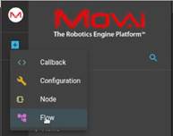
- Select the Flow option. The following displays –
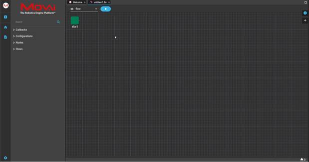
- Click anywhere in the flow diagram, as shown above. The following displays –
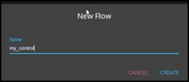
-
Enter the name of the flow and click CREATE to save this flow with the new name. In our example, we will call it my_control.
-
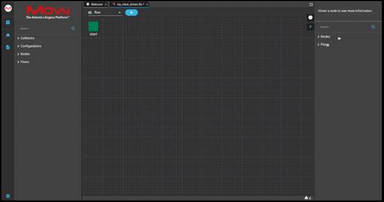
To instantiate a node into a template, expand the pane on the right by clicking
 , as shown below –
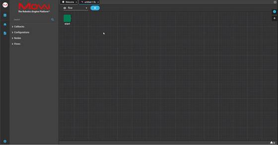
The following displays –
-
Expand the Flows branch in the right pane.
-
In the Search field above it, type any part of the name of the subflow that defines your robot drivers.
In this example, we will type the word my to find the my_robot_drivers subflow that we created, as described in Robot Drivers.
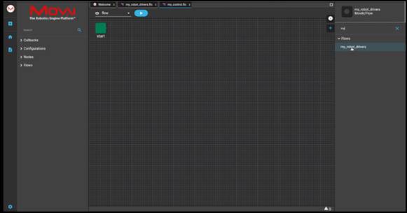
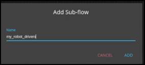
- Drag-and-drop the my_robot_drivers subflow from the left pane into the flow. A popup appears into which you must enter the name of this node instance.
-
In our example, we will leave the same name. Click the ADD button.
-
Drag and draw a link from the start node to the input port (dot) on the left side of the my_robot_drivers subflow node.
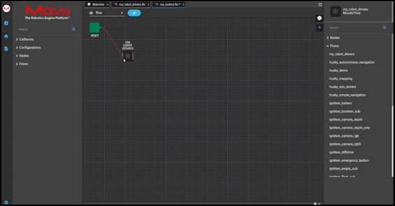
If you hover over this port, the information is displayed about the type of message that this port can send/receive. This enables you to determine to which input port (dot) on the left side of the my_robot_drivers subflow to draw the connection.
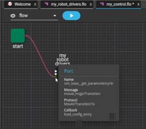
The left side of each node has a dot for each input port on the right side of each node has a dot for each output port.
The dots on the left of the my robot drivers node represent the input ports that we defined, such as for the diffdrive control node and so on.
The dots on the right side of the subflow node represent the output (publishing) ports that we defined, such as the camera, diffdrive optometry and so on.
The Nodes list in the right pane enables you to access all the nodes provided in the ROS community, as well as those added by MOV.AI and those that you have defined yourself in MOV.AI.
Note – You may refer to MOV.AI GD Nodes description (Coming Soon) for a description of all the nodes provided by MOV.AI. You may refer to Defining Nodes – Node Templates for a description of how to create your own nodes.
- To add a node that sends a command to the diffdriver –
- Search for the node named cmd_vel_pub.
- Drag it into the flow, as shown below –
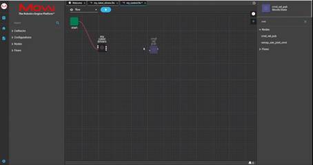
- Assign it a name or leave the name as is (as we did here).
- Drag and draw a connection from the output port of the my robot drivers node to the input port of cmd 1 in order to receive the output after the 5 seconds waited by the wait node.
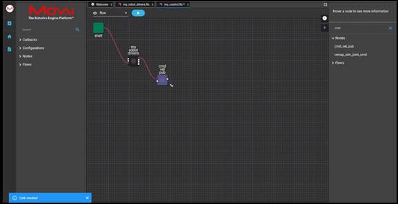
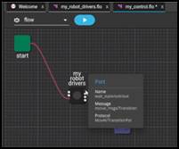
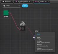
In order to know which port (dot) to connect to which port (dot) on each node, you can hover over the port on the node to see the type of messages that it can send or receive. For example, as follows –
- You can hover over the output port on the my_robot_drivers subflow to see the type of messages that it can send, as shown below –
- You can then hover over the input port of the cmd vel pub node to see the type of messages that it can receive, as shown below –
- The cmd 1 node has an output port named1 cmd_msgs_publisher that appears in the right Parameters pane in the Ports → Outputs section (as shown below), which publishes the message received from the diffdriver.
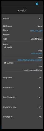
You can also see it by hovering over the relevant output port (dot), as shown below –

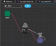
- Drag and draw a connection from the output port of cmd vel pub to the input port of the my robot drivers node, as shown below –
Connecting Nodes
Color-coded dots help you connect nodes according to the message type.
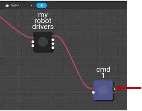
The dots that represent the ports of a node are color-coded to help you understand which ports can be connected. The white colored dots indicate ports that can be connected. For example, the cmd1 node has one white output port.
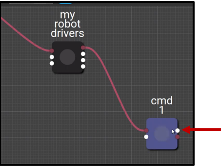
When you click on the white output port of the cmd 1 node it turns green to indicate that it is selected, as shown below –
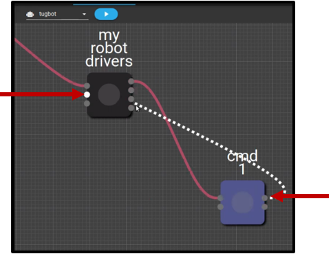
Start dragging and drawing a line from it towards the my robot drivers node. While you do so, it turns gray, as shown below.
Only one of the input ports of the my robot drivers nodes remains white indicating that this is the only one to which you can connect.
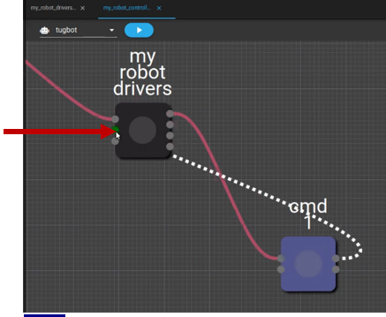
When you draw the end of the line so that it is hovering over the input port of the my robot drivers node, it turns green to indicate that this is a port to which it can connect, as shown below –
Watch this to see what we did above –
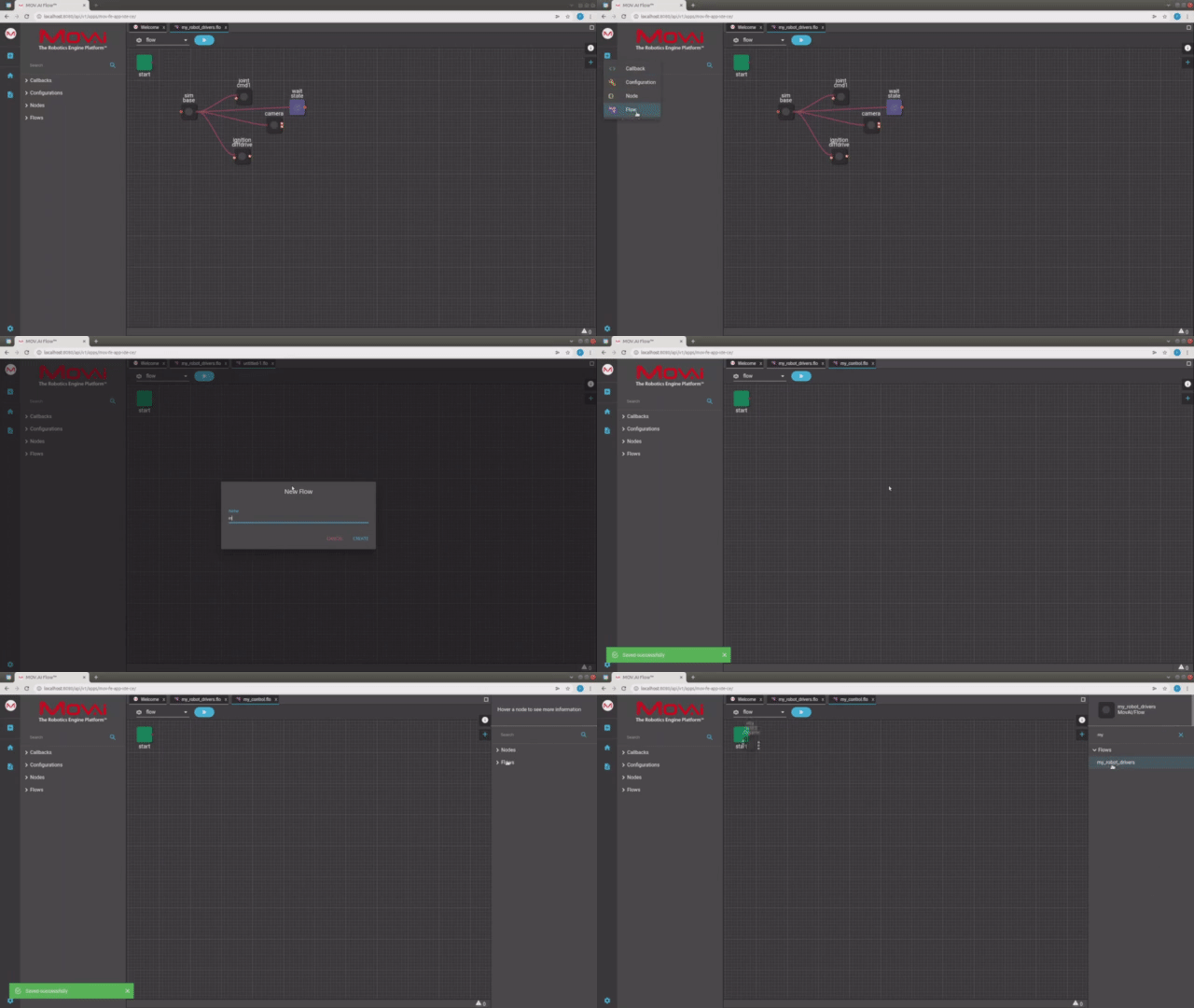
Here's a small taste. Click below to see the full video.
 Watch the next steps!
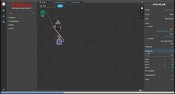
- Click the cmd vel pub node to configure its parameters in the right pane. Expand the Parameters section. The following displays –
- Use the Edit
 button to modify its parameters in order to specify the velocity of movement in each direction in meters per second – linear_x, linear_y and so on. This means that when the flow starts and it transitions to the cmd vel publish node, the robot will start moving at the velocity specified here. For example, the following shows how to modify the speed of the robot travels per meter in the X direction by editing the value in the linear_X parameter –
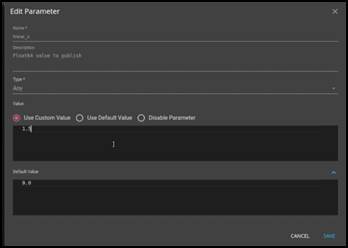
You can modify all these parameters in the same manner. For example, editing the angular parameter enables you to change the speed at which the robot turns.
-
In the same manner as above, you can add another output port from the cmd vel publish node, which can be drawn from the dot that represents the camera port.
-
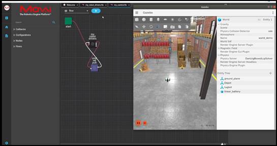
Redisplay the Tugbot world in Gazebo. If it’s not already open, then perform the following. Alternatively, you can launch the new world that you created in Gazebo using the same procedure as below.
- Open the MOV.AI Simulator Launcher, by clicking the following icon –\

The following displays –
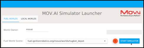
- In the Fuel World Scene dropdown menu, select fuel.ignitionrobotics.org/movai/worlds/tugbot_depot, as shown above.
- Start the simulation by clicking the START SIMULATOR button. The following displays –
Playing the Flow
Click on the Play  button to make everything play. Green dots should start flashing on the nodes in the flow and after a while the robot will start to move.
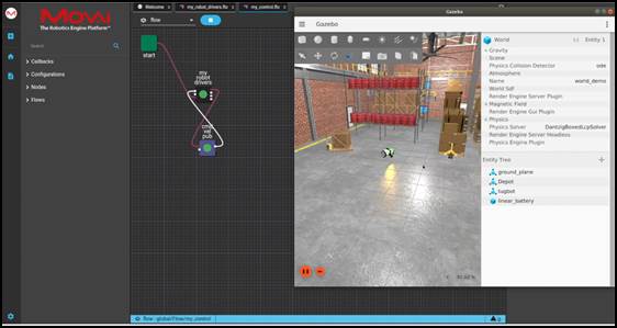
Watch this to see what we did above –
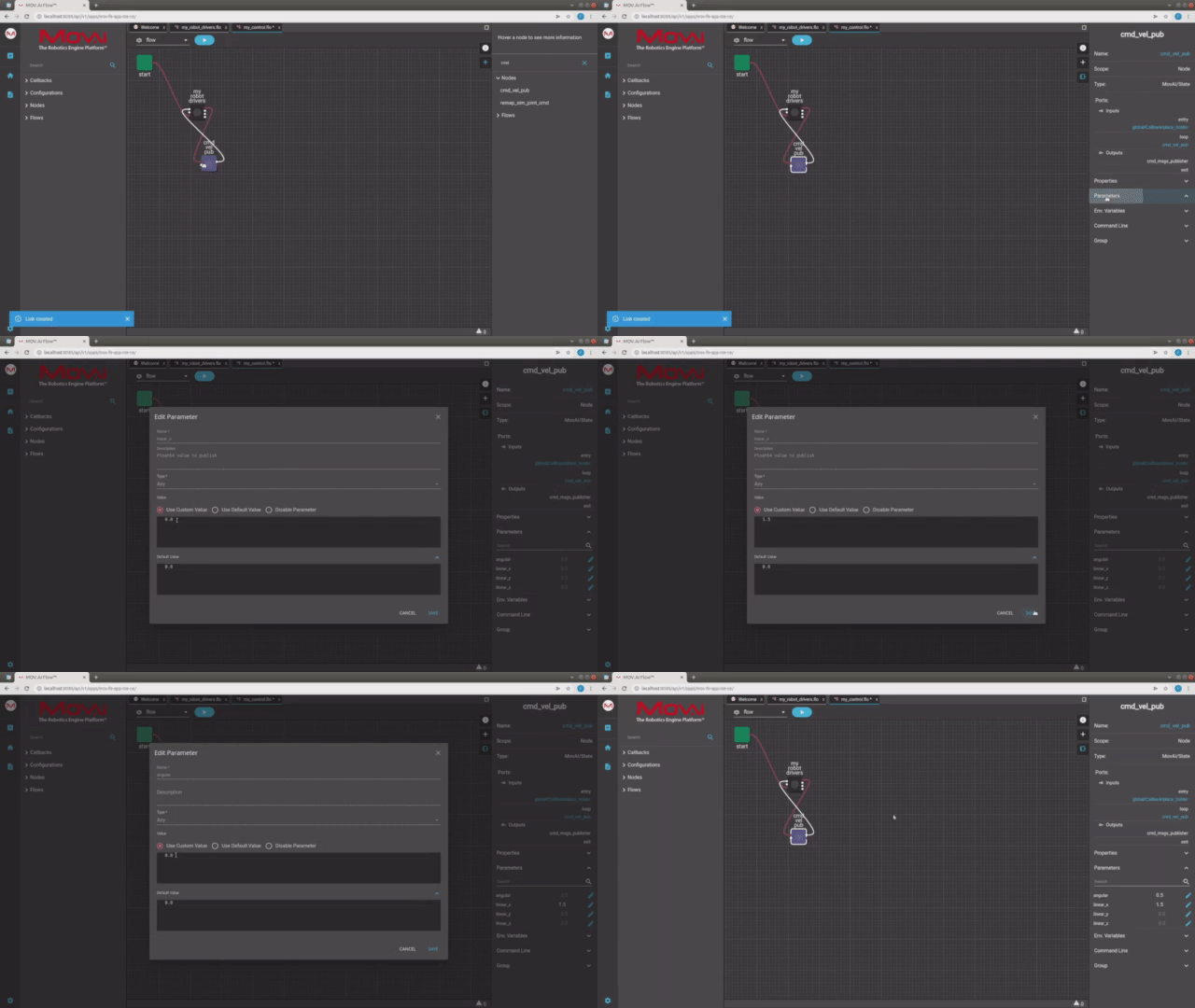
Here's a small taste. Click below to see the full video.
 Watch the next steps!
Updated 9 months ago
