Creating Simulated Robot ROS Drivers
The following walks you through the process of building a subflow that communicates with the sensors and controllers that will simulate your robot’s behaviors.
No Robot model yet?If you don't have a robot simulation (Gazebo Fortress model), follow this guide to build your own simulated robot Building a SIM Robot.
No Robot world yet?If you have a robot model, but it is not embedded into a Simulated World, follow this guide to see how to do it Building a Simulated World.
To start developing and simulating your own robot in MOV.AI Flow™, one of the first steps is to create the connection between MOV.AI Flow and the sensors of the robot in Gazebo Fortress. This enables MOV.AI's flows to receive the data from the simulated robot’s sensors (for example, its LiDAR and camera sensors), as well as to create the connection between MOV.AI Flow and the robot's controllers, so that MOV.AI's flows can control the robot (for example, its wheels and gripper).
Note – These things have already been done for you for Tugbot and Husky robots.
The connection between MOV.AI Flow and the robot in Gazebo Fortress (meaning the robot's drivers) is defined as a subflow in MOV.AI Flow, as described in this topic. This definition need only be done once. This subflow (robot drivers) can then be reused for a variety of scenarios that you design in MOV.AI Flow.
This page describes the creation of Tugbot-Simulated Drivers as an example.
Creating Simulation Robot Drivers in a MOV.AI FLOW Subflow
To create a connection between MOV.AI Flow and your robot in Gazebo Fortress –
- Launch MOV.AI Flow™, as described in Launching MOV.AI Flow™. The following displays –
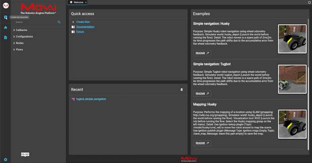
- Click the Create New Document
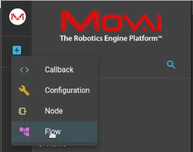
 button in the top left corner, as shown above. The following menu displays –
-
Select the Flows option.
-
Click anywhere in the flow diagram, as shown below –
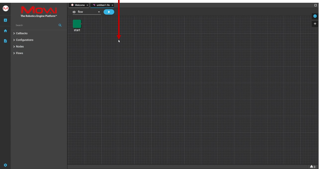
The following displays –
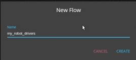
- Enter the name of the flow and click CREATE to save this flow with the new name.
Watch this to see what we did above –
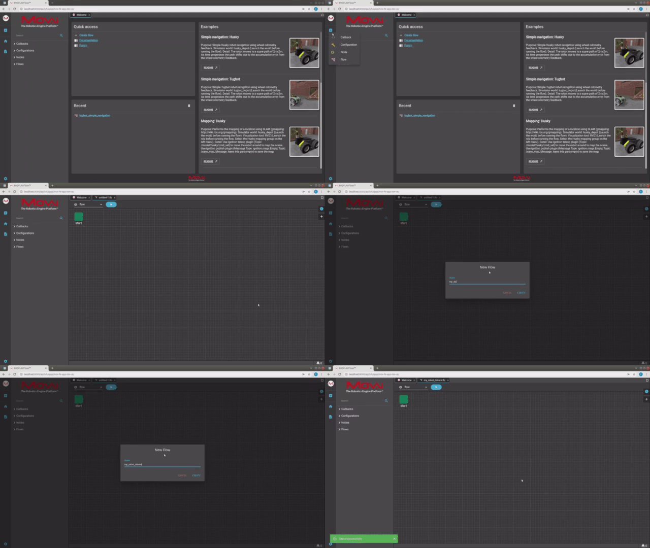
Here's a small taste. Click below to see the full video.
 Watch the next steps!
Note – The objective is to build something like the following which defines the connection between the simulated robot and MOV.AI Flow.
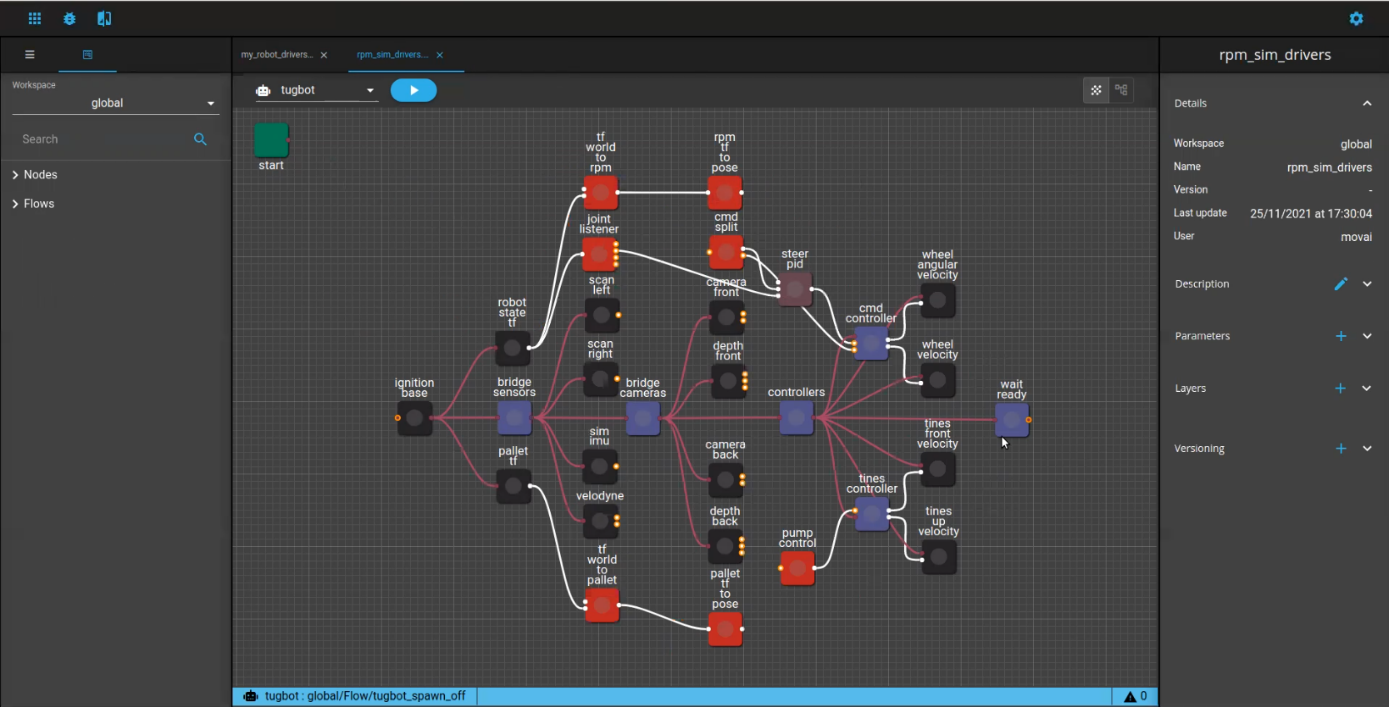
Adding Nodes to the Subflow
MOV.AI Flow provides a variety of ready-made nodes to support the integration with Gazebo Fortress. The name of each such node starts with the string Ignition_. The following describes how to add an instance of these node templates into your subflow.
Each node provided by MOV.AI Flow acts as a template that can be instantiated in the flow when it is dropped there.
To add the nodes that comprise the subflow –
- To instantiate a node into a template, expand the pane on the right by clicking
 , as shown below –
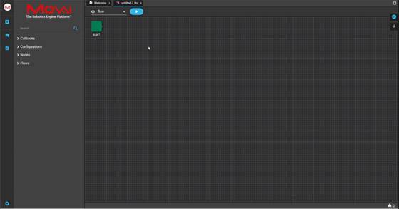
The following displays –
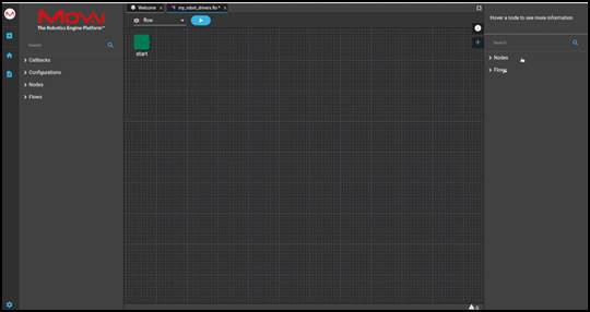
-
Expand the Flows branch in the right pane.
-
In the Search field above it, type the word ignition to see a list of the nodes provided by MOV.AI Flow to support integration with Gazebo Fortress.
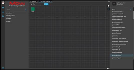
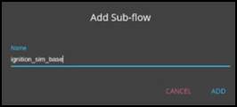
- Drag-and-drop the Ignition sim base node from the left pane into the flow. This must be the first node to be added to the subflow so that it can use the clock from the simulator and set the initial parameters for this subflow. A popup appears into which you must enter the name of this node instance.
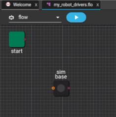
The following shows that node after it has been renamed sim base.
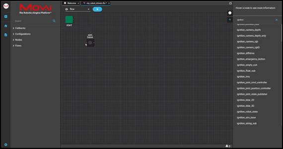
- After you have defined the subflow that enables MOV.AI Flow to interact with the robot defined in the Gazebo Fortress simulator, you must expose the ports of each node in this subflow (my_robot_drivers) so that it can be used as part of a main flow (tugbot_sim_demo) that will call it in order to interact with the simulator.
To expose the ports that enable this node (which is inside a subflow) to communicate with the flow that called this subflow and with the other nodes in this subflow –
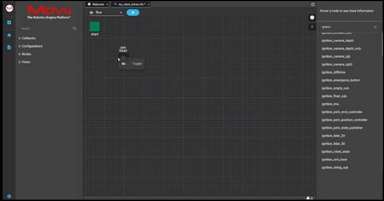
5.1 Right-click on the dot on the left side of the sim base node and select Toggle from the displayed menu, as shown below, in order to expose this port. This means that when you use this subflow in a parent flow, this port will be exposed, meaning that it will be available for selection from the main flow.
5.2 This is the entry point from the main flow to this subflow. If you hover over this port, the information is displayed about the type of message that this port can send/receive, as shown below –
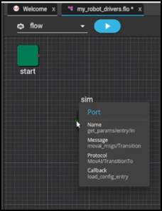
Note – Each node provided by MOV.AI Flow in the left pane acts as a template that is instantiated in the flow when it is dropped there. As soon as you drop it into the flow diagram, a popup appears in which to name this node instance. That’s why the name of the nodes that you see in our example flows are slightly different than the node templates listed in the left pane. For example, Ignition_sim_base vs. sim base.
FYI – Double-clicking the sim base node drills down to display the nodes contained in its subflow, as follows. For example, this subflow contains the clock node that enables you to get the clock from the simulation. There is no need to do anything in this node.
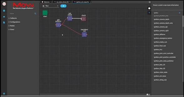
- Click on the my_robot_drivers.flow tab at the top of the page to return to the page defining our subflow. The following displays –
Watch this to see what we did above –
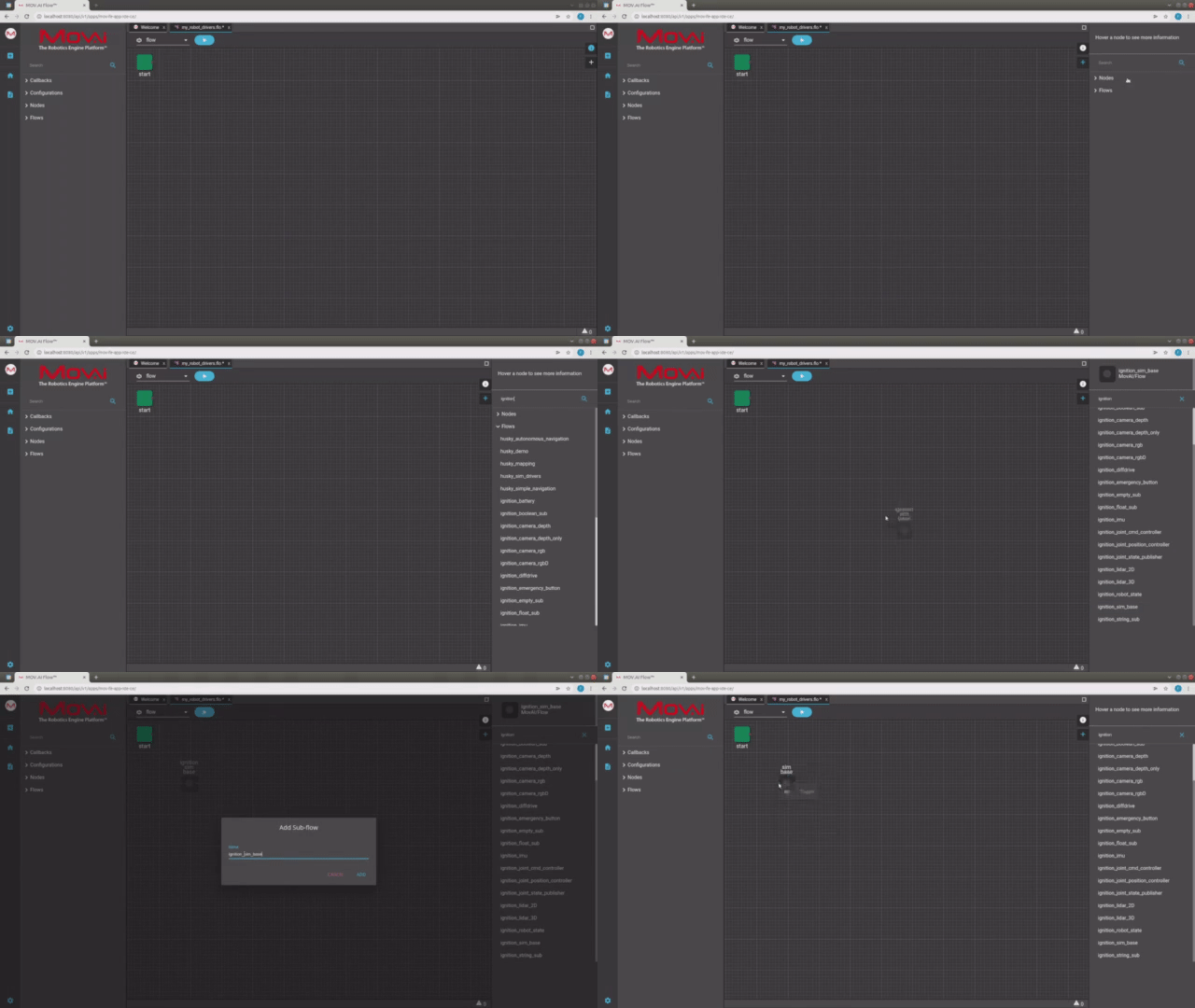
Here's a small taste. Click below to see the full video.
 Watch the next steps!
-
Start defining the Ignition_sim_base subflow (which is called sim base) by adding a node for each controller that is in the robot (as defined in the SDF file and as described in the subflow, as described The Nodes of a MOV.AI Flow Tugbot Subflow).
Let’s add the controller for the wheels (diffdrive). This node is provided by MOV.AI Flow and is named Ignition_diffdrive.
To add this node to the flow, search for the word Ignition and find the Ignition_diffdrive node, as shown below –
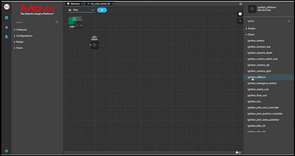
- Drag the Ignition_diffdrive node into the flow and give it a name, as shown below –
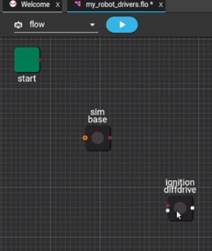
-
Each node represented in a flow has inputs on the left and outputs on the right, each represented by a dot. The red dots must be connected in order to represent the flow of information from one node to another.
Drag and draw a connection from the output of the sim base node (the dot on its right) to the input of the diffdrive node (the dot on its left).
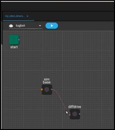
- In order for the robot to be controlled from outside this subflow, expose the ports of each of its drivers and sensors.
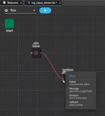
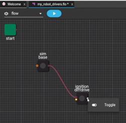
- Right-click on the port on the left side of the diffdrive node and select Toggle so that it can receive a command from the flow that calls this subflow. For example, to control the speed of the robot.
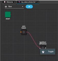
You can hover over it to see the type of message that is sent, as shown below –
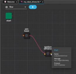
Right-click on the output port on the right side of the diffdrive node so that it can publish (send) the odometry of the robot’s movement.
You can hover over it to see the type of message that is sent, as shown below –
Watch this to see what we did above –
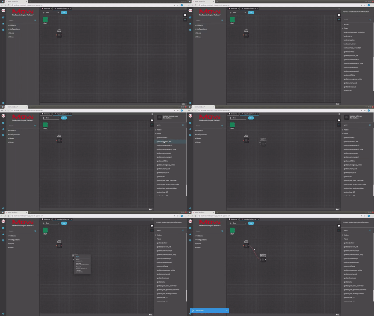
Here's a small taste. Click below to see the full video.
 Watch the next steps!
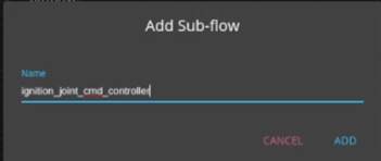
- Add the joint controller (in the same way as described above) by searching for the string ignition and then dragging the ignition_joint_cmd_controller into the flow diagram. In this example, it is renamed joint1 cmd, as shown below –
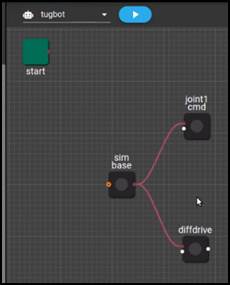
- Drag and draw a connection from it to the sim base node. The flow diagram should now appear as follows –
-
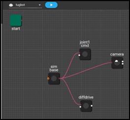
Add an RGB camera node (in the same way as described above) by searching for the string ignition and then dragging the ignition_camera_rgb node into the flow diagram. In this example, it is renamed camera.
-
Drag and draw a connection from it to the sim base node. The flow diagram should now appear as follows –
- Expose the input port of the joint1 cmd node in order to enable a main flow to control the gripper –
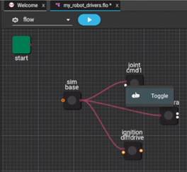
- You can hover over it to see the type of message that is sent, as shown below –
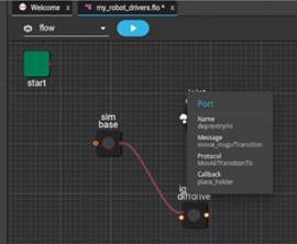
Note – There is no output port for the joint1 cmd node, because the Tugbot robot’s gripper does not have a
sensor that captures information that can be published.
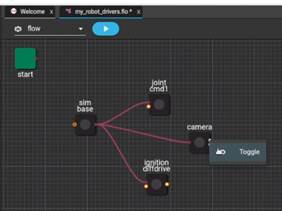
- Expose the output port of the camera so that it can publish the image that it captures, as shown below –
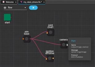
- You can hover over it to see the type of message that is sent, as shown below –
Watch this to see what we did above –
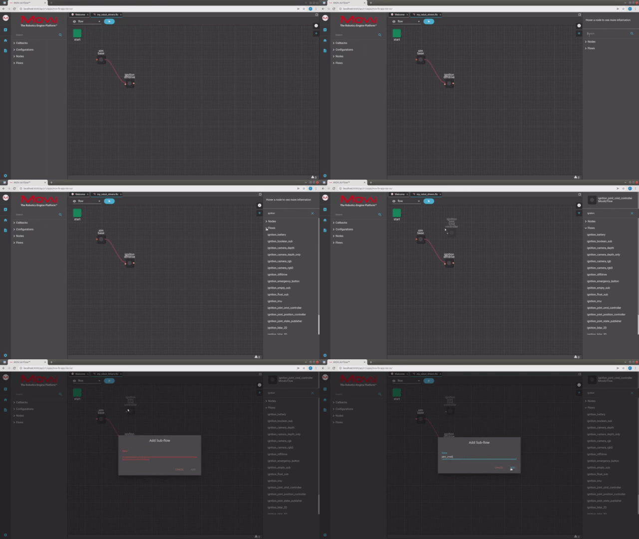
Here's a small taste. Click below to see the full video.
 Watch the next steps!
- Continue as described above to add and connect all the controllers that you defined in the SDF file.
After all the ports of the sensors have been exposed to receive input commands and to publish the data that their sensors collected, this subflow can be used by a parent flow that controls the robot
- This subflow (named my_robot_drivers) is called from the main flow (named tugbot_sim_demo) and then returns back to that main flow. This subflow starts executing it from the sim base node and then flows to each of the sensor/joint controller nodes.
This subflow receives commands from the main flow that are intended to be executed by the simulated robot; and then this subflow must send information from the simulated robot’s sensors back to the main flow.
In order to make sure that all the controllers are launched before this subflow returns back to the main flow, a wait node should be added to the flow diagram.
To add a wait node to the flow diagram –
- Expand the Nodes branch.
- Search for the word wait , as shown below –
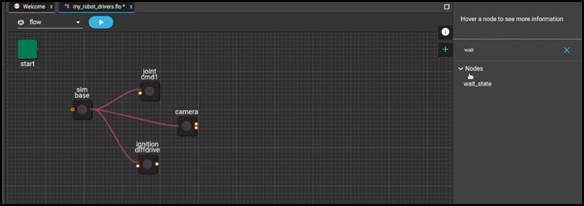
- Drag the wait node into the flow diagram and give it a name. The flow diagram should now appear as follows –
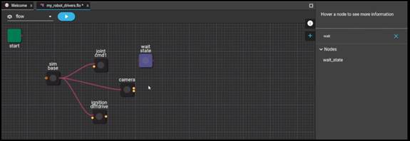
- The following describes how to modify the wait_time property in the right pane to specify that the flow waits 5 seconds before sending anything to the output port of this flow. To modify the wait_time property –
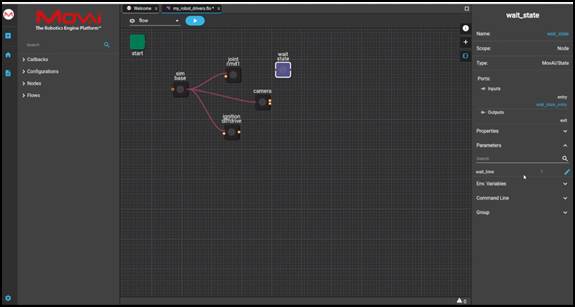
- Click on the wait node in the flow diagram to display the pane of properties on the right.
- Click on Parameters
 to expand it to show all the customizable parameters provided for this node. For example, as shown below –
- Click the Edit
 button next to the wait_time parameter. The following displays –
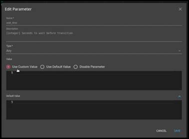
- Check the Use Custom Value radio button in the popup that displays.
- Change the value 5 to 10 seconds.
- Click the Save button.
- Drag and draw a connection from it to the output port of the sim base node to the input port of the Wait node. The flow diagram should now appear as follows –
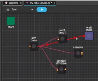
- You can hover over it to see the type of message that is sent, as shown below –
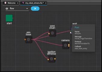
- Right-click on the right side of the wait node and select Toggle in order to expose the last (exit – output) port of this subflow, as shown below –
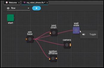
Both the sim base node and the wait node appear with an orange dot to indicate that they are exposed, as shown below –
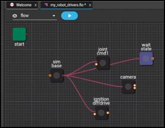
Watch this to see what we did above –
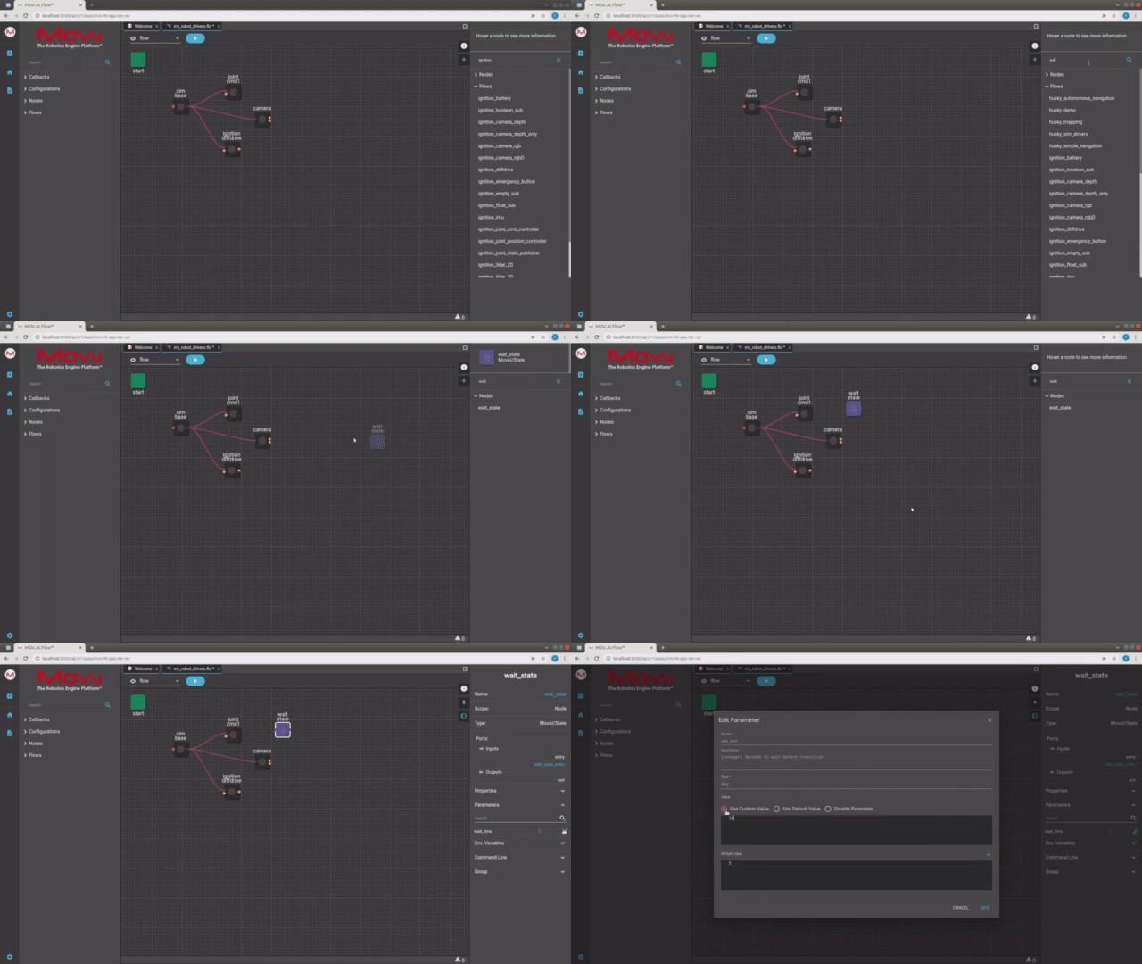
Here's a small taste. Click below to see the full video.
 Watch the next steps!
Configuring the Nodes
The following describes how to configure a controller/plugin, a joint and a sensor. There’s no need to configure a link, because it’s simply an object for you to control, meaning that it does not have its own controller.
Configuring a Controller
To configure a controller in the flow diagram –
- Redisplay the Tugbot world in Gazebo. If it’s not already open, then –
- Open the MOV.AI Simulator Launcher, by clicking the following icon –

The following displays –

- In the Fuel World Scene dropdown menu, select fuel.ignitionrobotics.org/movai/worlds/tugbot_depot, as shown above.
- Start the Simulation by clicking the START SIMULATOR button. The following displays –
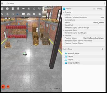
- Define the name of the robot in the MOV.AI Flow, as follows –
- In Gazebo, click on the robot’s picture in the world to display its name in the pane on the right. In this example, the robot’s name is Tugbot, as shown below –
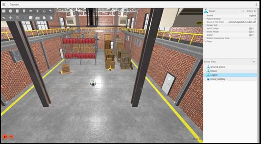
-
In MOV.AI Flow, click the ignition diffdrive node in the flow diagram to display its properties in the pane on the right.
-
Expand the Parameters option to display this node’s parameters, as follows –
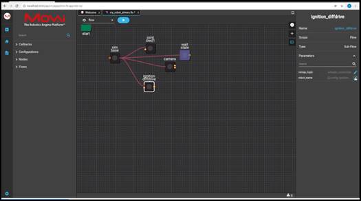
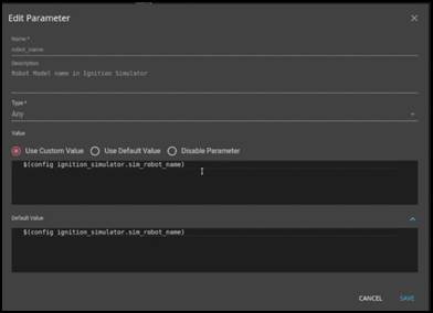
- In the robot_name parameter, specify the robot name that was defined inside the SDF file and in Gazebo by clicking its Edit
 button. The following displays in which you can enter the value to be used –
-
Click the Use Custom Value radio button.
-
Replace the entire string that is displayed with the name of the robot, which is tugbot. For example, as shown below –
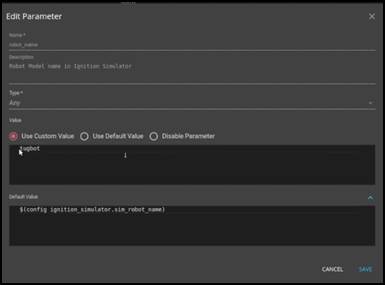
- Click the Save button.
- Repeat this same process of entering the robot’s name (which is tugbot) into the robot_name of each of the controller and sensor nodes in this flow. In our example this would mean joint cmd1 and camera.
Watch this to see what we did above –
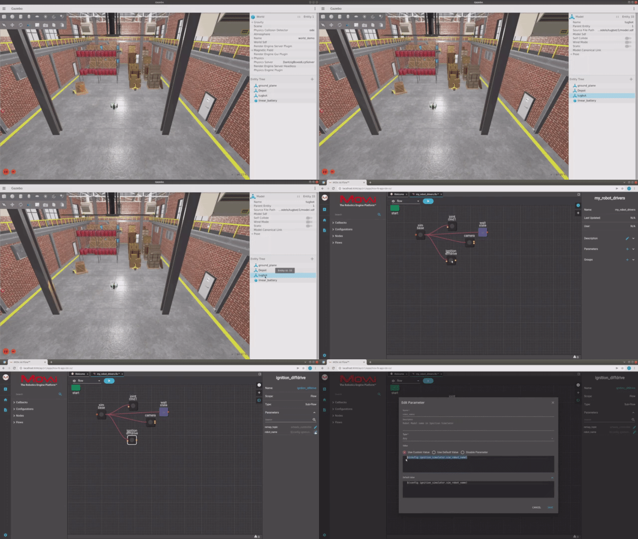
Here's a small taste. Click below to see the full video.
 Watch the next steps!
Remember that the name of the robot is specified in the SDF file here –
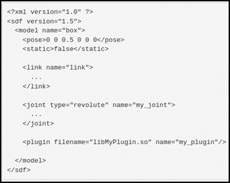
Alternatively, you can find the name of the robot in Gazebo Fortress by searching for Entity Tree in the top right corner, as shown below –
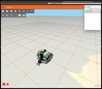
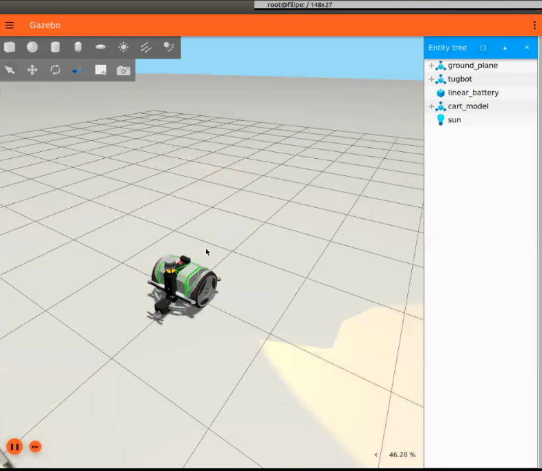
The robot’s name appears in the tree as a  icon, as shown below. In this example, the name of the robot is tugbot.
You can expand the robot branch  to show all the links and joints that were defined in the SDF file, as shown below –
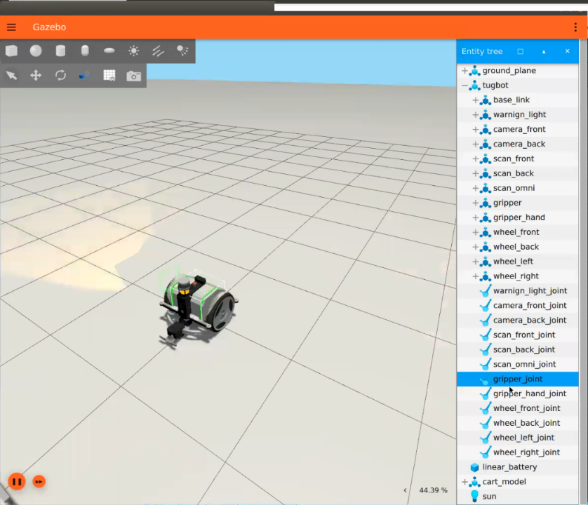
You can also expand the branch of a link or a joint to see its components, such as is visual and collision.
-
It’s not necessary, but you can also change the default value of the remap_topic in the same manner as shown above.
-
Repeat the process above for every controller.
Configuring a Joint
To configure each joint node defined in the SDF file –
-
To configure a joint node in the SDF file, click on the joint node in the flow diagram. For example, click on the node named joint1 cmd to display its properties in the pane on the right.
-
Expand the Parameters option to display this node’s parameters, as follows –
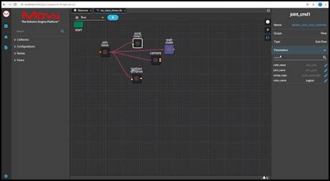
- Joint_name – Specify the name of the joint (as defined in the SDF file) represented by this node.
- Child_name – Specify the name of the link (as defined in the SDF file) to be controlled by this node.
- remap_topic – There is no need to change this value.
- robot_name – Specifies the robot name that was defined inside the SDF file. In this example, it is tugbot.
For example, in Gazebo Fortress, in order to control gripper_joint (as described below), you must know the name of the link that this joint controls, so that in the joint_name property you can enter the name of that joint as it is specified in the SDF file; and in the child_name property, you can enter the name of the link controlled by this joint as it is specified in the SDF file.
For the Tugbot, to edit the name of the joint node named joint1 cmd, in the right pane, click the Parameters option to display the parameters of this node and then click the Edit ![]() button to the right of each of the parameters.
button to the right of each of the parameters.
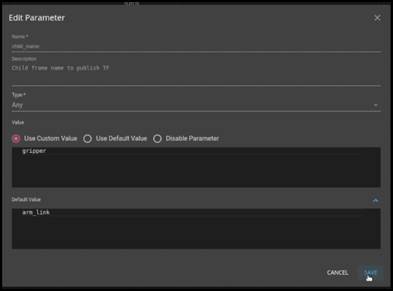
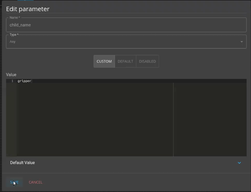
For example, for the child_name parameter specify the name of the link controlled by the gripper_joint to be controlled by this node as it is defined in the SDF file. The following displays. Replace the displayed value with gripper and click SAVE.
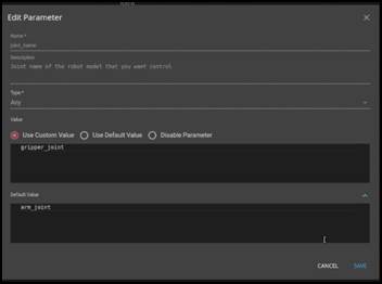
For example, for the joint_name parameter. The following displays. Replace the displayed value with gripper_joint and click SAVE. The following displays –
You can also change the remap_topic parameter in the same manner. This is a ROS name so that you can change its value to anything you want.
Watch this to see what we did above –
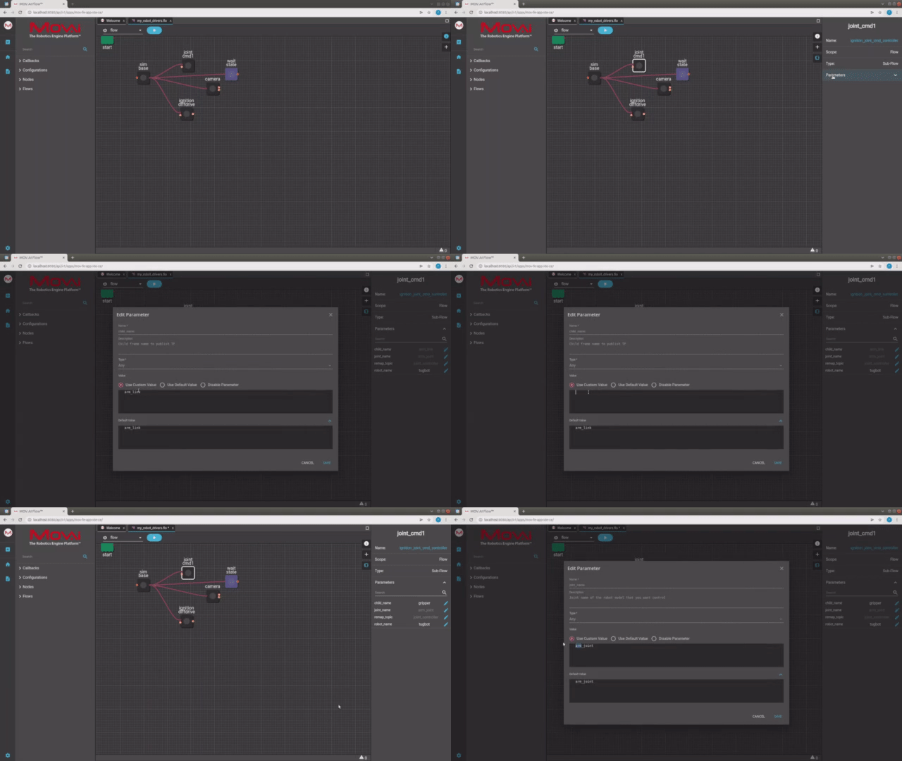
Here's a small taste. Click below to see the full video.
 Watch the next steps!
If you don’t remember its name, then here’s how to find it –
- Open the SDF file and search for the name of the plugin, which is JointController, as shown below –

In this example, the code shows that the joint_name is gripper_joint.
- Search for gripper_joint to see which link this gripper joint controls.
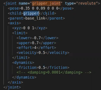
In this example code, the code shows that the child property is gripper.
- Go back to MOV.AI, and in the child_name property enter gripper, as shown below –
- Repeat the process above for every joint.
Configuring a Sensor
To configure each sensor defined in the SDF file –
- In MOV.AI, click on a sensor node (for example, the camera node) in order to display its parameters in the pane on the right and then click the Parameters option to expanded to display the parameters. The following displays –
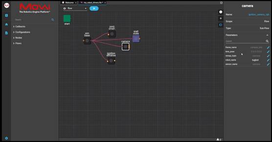
- To find the definition of this camera sensor in the SDF file, search for the name of the link inside which the camera is located. In this example, its name is camera_front. In our example SDF file, this link contains two sensor’s – a camera named color and a depth_camera named depth.

In this example, we only create the subflow of the color camera.
The following shows an expansion of the sensor definition named color –
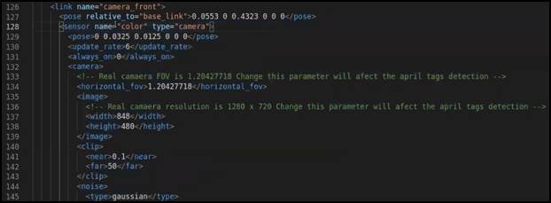
The sensor tag contains all the values that are required to describe this camera according to standard SDF file conventions, such as –
- horizontal_fov – Specifies the horizontal length of the image at a given distance from the lens.
- image resolution – Specifies the width and height of the captured image.
- clip – Specifies how near or far away the camera detects objects.
- noise – Specifies whether to simulate the noise of a real camera sensor.
- Lens – Specifies intrinsic parameters that come from the specifications of the actual camera.
- In MOV.AI, define the following according to the values in the SDF file –
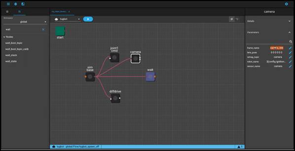
Use the Edit ![]() button to edit each of the following parameters –
button to edit each of the following parameters –
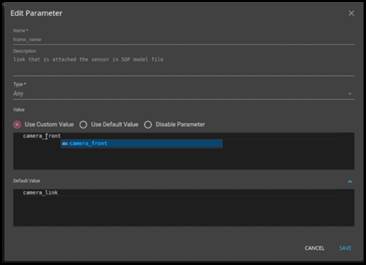
- Frame_name – Specifies the name of the frame, to which the camera is attached (meaning its link) and as defined in the SDF file. In this example is camera_front, as shown below –
- lens_pose – Use this to specify that the lens is in a different position relative to the camera’s frame (for example, if the lens is not in the center of the camera). This parameter is measured in meters – X, Y, Z, roll, pitch, yaw.
- remap_topic – There is no need to change this value.
- robot_name – Specifies the robot name that was defined inside the SDF file. In this example, it is tugbot.
- sensor_name – Specifies the name of the sensor, which in this example is color.
- Repeat the process above for every sensor.
Watch this to see what we did above –
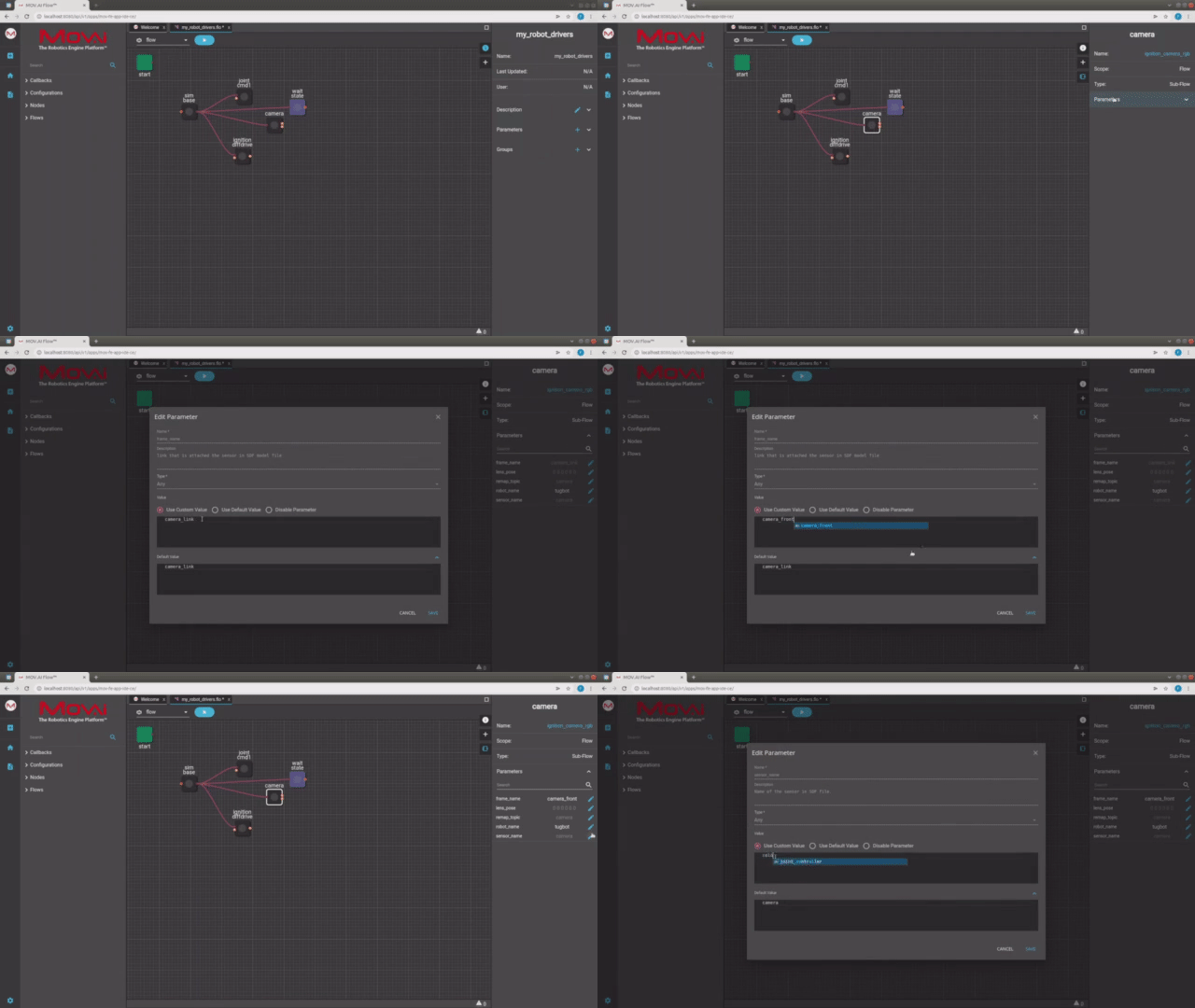
Here's a small taste. Click below to see the full video.
 Watch the next steps!
Updated 9 months ago
