Tugbot Sensors and Actuators Nodes – Full Example
A subflow that connects MOV.AI to a robot in the Gazebo Fortress simulator should be created after you have defined your robot (including its sensors and controllers/plugins) in an SDF file (as described in Workflow – Creating a Simulation in MOV.AI) and have and have defined the environment in which the robot will operate (as described in Defining a Robot’s World).
Open your model in Gazebo Fortress. For example, here’s the Tugbot robot.
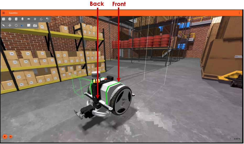
Note – You may refer to https://tugbot.ai/ for more information about the Tugbot robot.
For the purpose of our simulation, here’s a few of Tugbot features –
- Two depth camera sensors – one at the front and one at the back, as shown above.
- Two planar linear distance sensors (LiDARs) provide distance information – one at its front and one at its back.
- A 3D LiDAR on its top that provides 3D distance information.
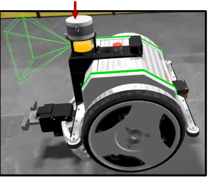
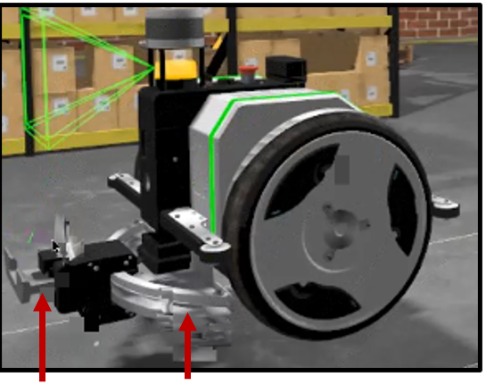
- Wheel Controllers – diff_driver controller. See http://wiki.ros.org/diff_drive_controller for more information.
- Gripper Controller – Controls the position of the Tugbot gripper along its arced bar.
Launch MOV.AI Flow, as described on Launching MOV.AI Flow™.
This guided tour shows you how to open a ready-made flow created by MOV.AI and to view the part of that flow (called a subflow) provided by MOV.AI to enable simple integration with the Gazebo Fortress simulator.
Listening to Robot Sensor Outputs
MOV.AI’s transparent integration with Gazebo Fortress enables MOV.AI’s flows to receive and react to the outputs of the simulated robot’s sensors.
MOV.AI provides the tugbot drivers node (shown below), which can be dropped into any MOV.AI flow so that it can listen to the data sent from the output port of each of a Tugbot’s sensors. This node represents the subflow that enables communication with the robot in the Gazebo Fortress simulator.
Open the provided flow called tugbot_sim_demo in MOV.AI Flow by double-clicking on it. The following displays –
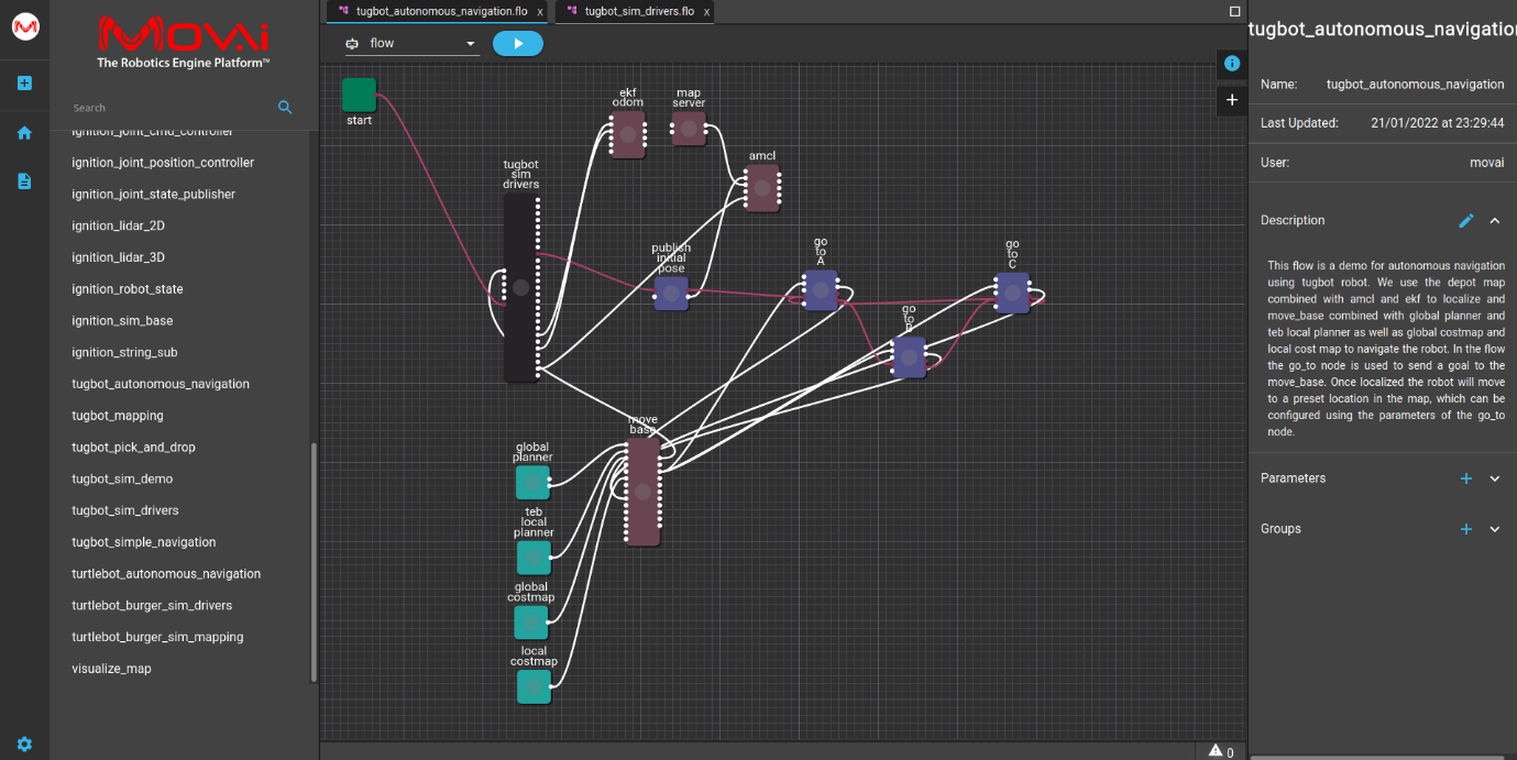
In this example flow, the cmd vel move node is connected to the tugbot drivers node. The cmd vel move node is a simple controller created and provided in MOV.AI that sends velocity control commands to a robot’s wheels. It uses the tugbot drivers node (which represents the tugbot_sim_drivers subflow) to communicate with the robot in the Gazebo Fortress simulation.
Note – The tugbot drivers node is just one of the many nodes provided by MOV.AI that you can use in any flow that you wish to create. For a detailed description of each of the ready-made nodes provided by MOV.AI, refer to the MOV.AI Node Description for the ROS Community – Coming Soon.
Let’s drill down to the tugbot_sim_drivers subflow –
You can use this subflow as isto interact with a Tugbot robot.
The remainder of this topic walks you through a quick tour of this subflow so that you can learn how to build your own. More details about building your own subflow provided in Creating Simulated Robot ROS Drivers.
Double-clicking on the tugbot drivers node displays the ready-made subflow that enables integration with the Gazebo Fortress simulator, as shown below –
 Watch the steps!
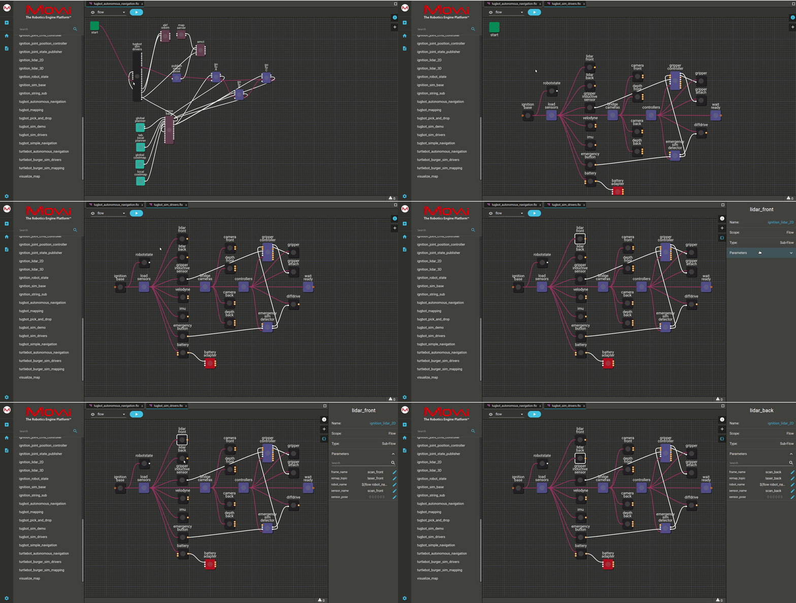
This flow diagram shows the connections between each of the Tugbot sensors.
- load sensors – In order to receive data, this node is connected to the following Tugbot measurement sensors (each which is each represented by a black colored node) – lidar front, lidar back, gripper inductive sensor, velodyne (3D LiDAR), imu (Inertial Measurement Unit inside the robot) and the battery sensor.
- bridge cameras – In order to receive data, this node is connected to the following Tugbot cameras – camera front, depth front, camera back and depth back.
Note – Nodes whose code can be viewed/edited by you appear in the flow diagram in purple. Nodes that subflows appear in black.
Here’s an example of how the Gazebo Fortress simulator recreates and displays the information received from the robot’s sensors in the simulated environment.
In the Gazebo Fortress simulator, you can mark the Display Lidar Visual checkbox to show the information picked up by the robot’s linear distance sensors (LiDARs), shown in blue below. LiDAR sensors can be used for a variety of purposes, such as to enable a robot to detect obstacles and people walking by so that it can change course or to detect a cart that needs to be picked up.
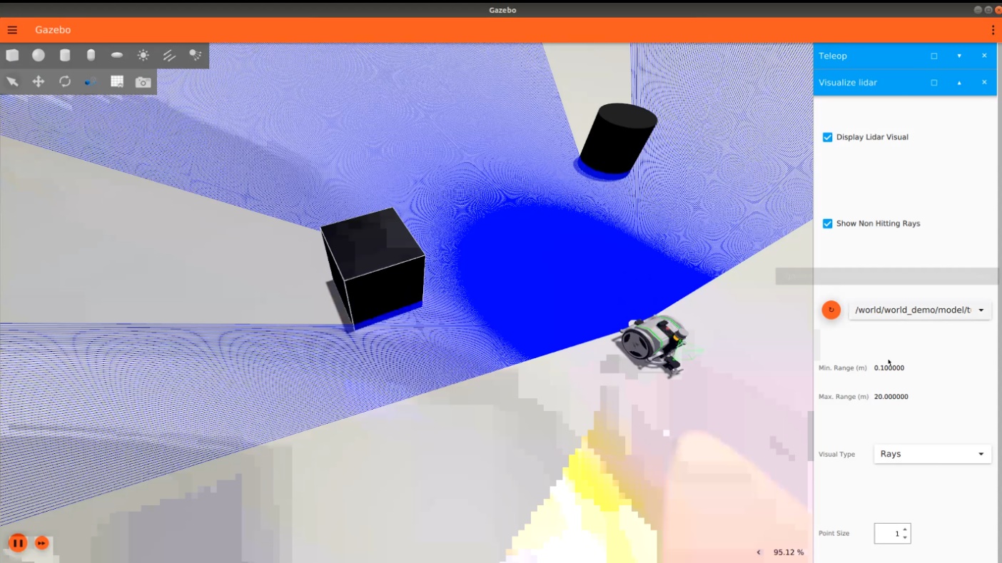
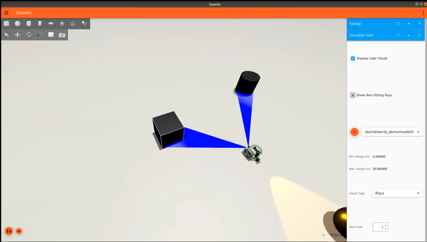
For example, marking the Show Non Hitting Rays checkbox visualizes the LiDAR sensors as follows in order to only show the LiDAR rays that are sensing (hitting) objects –
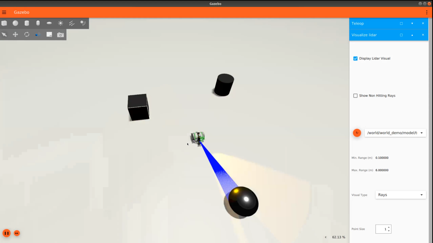
For example, to visualize the robot’s back LiDAR sensor, select the robot’s back sensor from the dropdown menu –
Controlling the Robot – Sending Commands to Its Controllers
MOV.AI has transparently integrated with the Gazebo Fortress simulator so that it listens for commands from MOV.AI’s flows and executes and visualizes them in the simulated scene.
MOV.AI has already defined this for you for a Tugbot robot. The tugbot driversnode is already integrated with the Gazebo Fortress simulator so that the controllers of the simulated robot are waiting for commands from MOV.AI. For example, the wheels are waiting for commands to turn and the gripper is waiting for commands to grip or release.
Watch this to see how a MOV.AI Flow controls a robot in the Gazebo Fortress simulator.
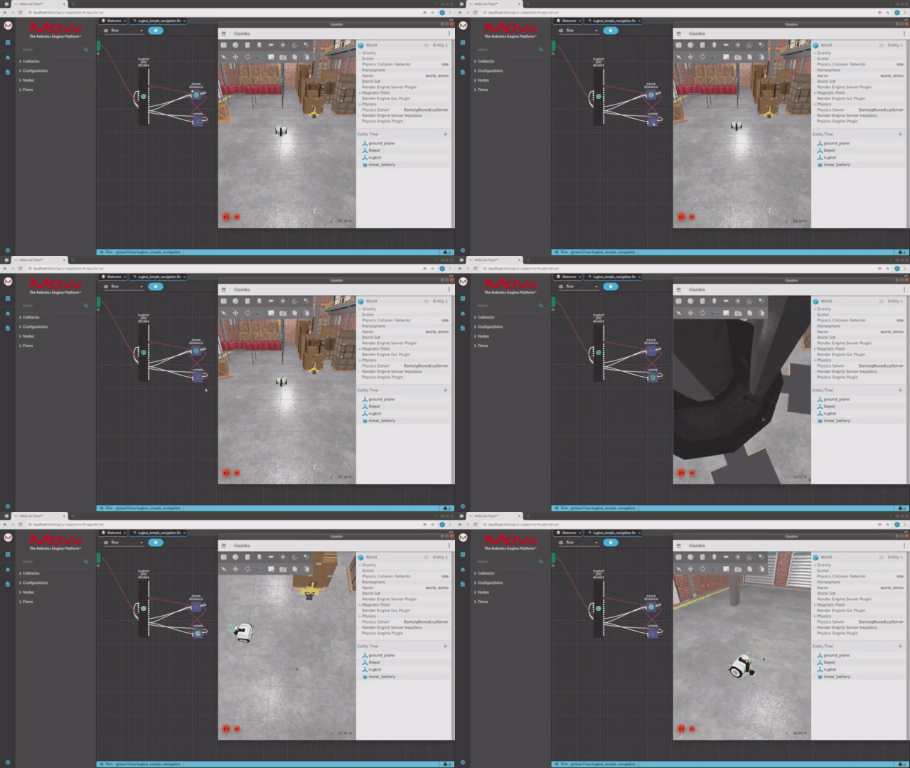
Here's a small taste. Click below to see the full video.
 Watch the steps!
To follow along in MOV.AI Flow and Gazebo Fortress –
-
If needed, install MOV.AI, as described in Installing MOV.AI Flow™.
-
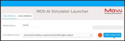
To open the MOV.AI Simulator Launcher, click the following icon –

The following displays –
-
In the Fuel World Scene dropdown menu, select fuel.ignitionrobotics.org/movai/worlds/tugbot_depot, as shown above.
-
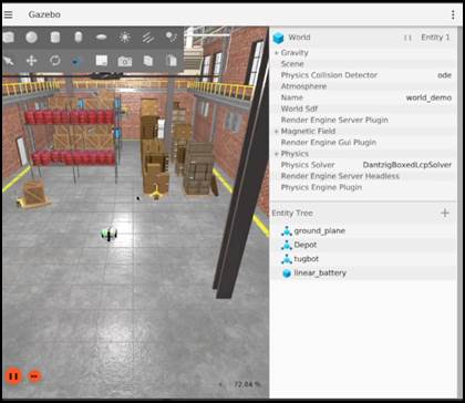
Start the simulation by clicking the START SIMULATOR button. This downloads the scene from Fuel and opens this environment in Gazebo, as shown below.
If this is the first time you are doing this, then it may take a while to appear, so please wait until the following displays –
- To open the flow in MOV.AI that will control the robot in the simulation open the Simple Navigation: Tugbot demo, by clicking on it on the following page –
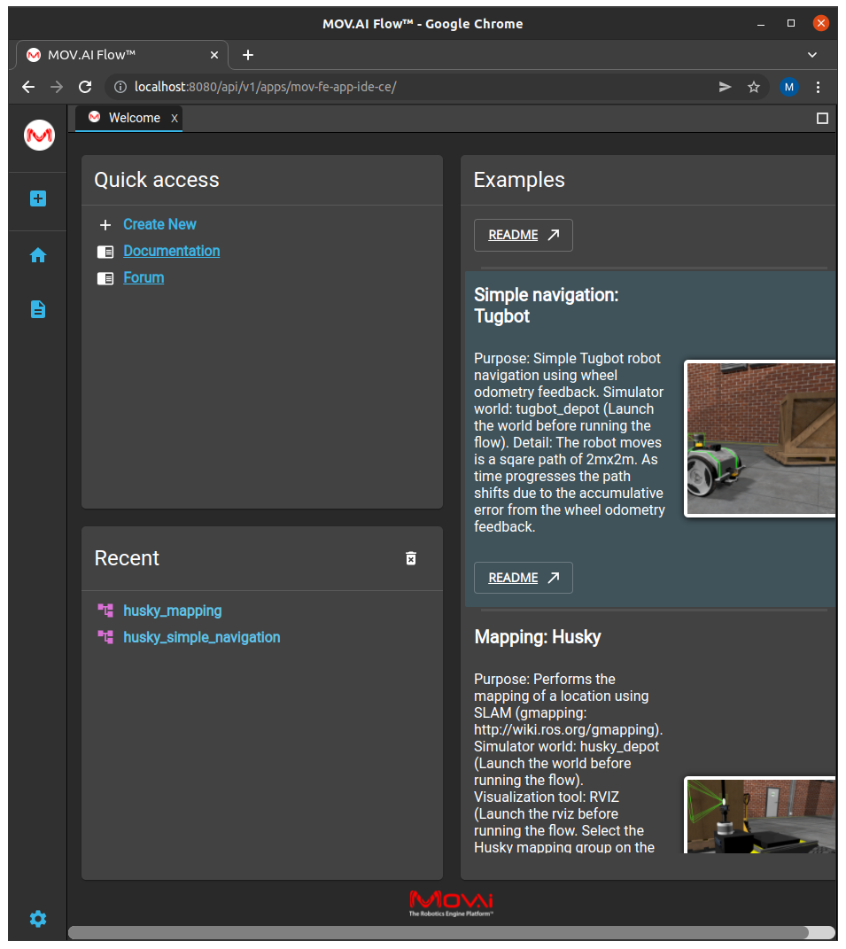
The following displays –
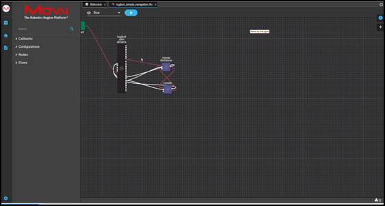
- Click the Play
 button. The following displays, which enables you to watch while the MOV.AI flow controls the robot in the Gazebo simulator –
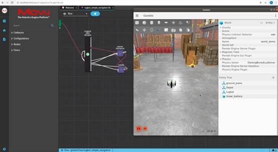
-
The move_distance node in the MOV.AI Flow sends a command to the simulated robot to move its wheels according to the node’s parameters, such as velocity and distance.
When the move_distance node starts to display a green flashing dot, the robot starts moving in the Gazebo simulator.
The robot moves forward, stops and turns right repeatedly so that it is traveling around in a square pattern.
As you can see, the move_distance node connects to the rotate node and the rotate node connects to the move_distance node in a closed loop. This is represented by the red lines connecting between these two nodes, as shown below –

This means that the robot continuously travels in square patterns until you stop the simulation or the flow.
This flow also shows a connection (shown as redlines below) between the move_distance node and the tugbot sim drivers subflow (in black).
The move_distance node publishes a velocity command to the tugbot sim drivers subflow. You can see information about this message and protocol, by hovering over the relevant port of the tugbot sim drivers subflow, as shown below –
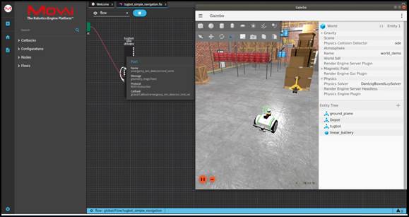
The rotate node also publishes a velocity command to the same port of the tugbot sim driverssubflow. You can see information about this message and protocol, by hovering over the relevant port.
Controlling the Robot’s Behavior
The following shows how easy it is in MOV.AI flow to change a robot’s behavior by simply changing parameters in the MOV.AI flow user interface.
For example, the following shows how you can change the number of meters that the robot travels in each direction, as well as the angle that it turns (rotates).
Watch this to see how easy it is to figure a robot’s behavior in the user interface –
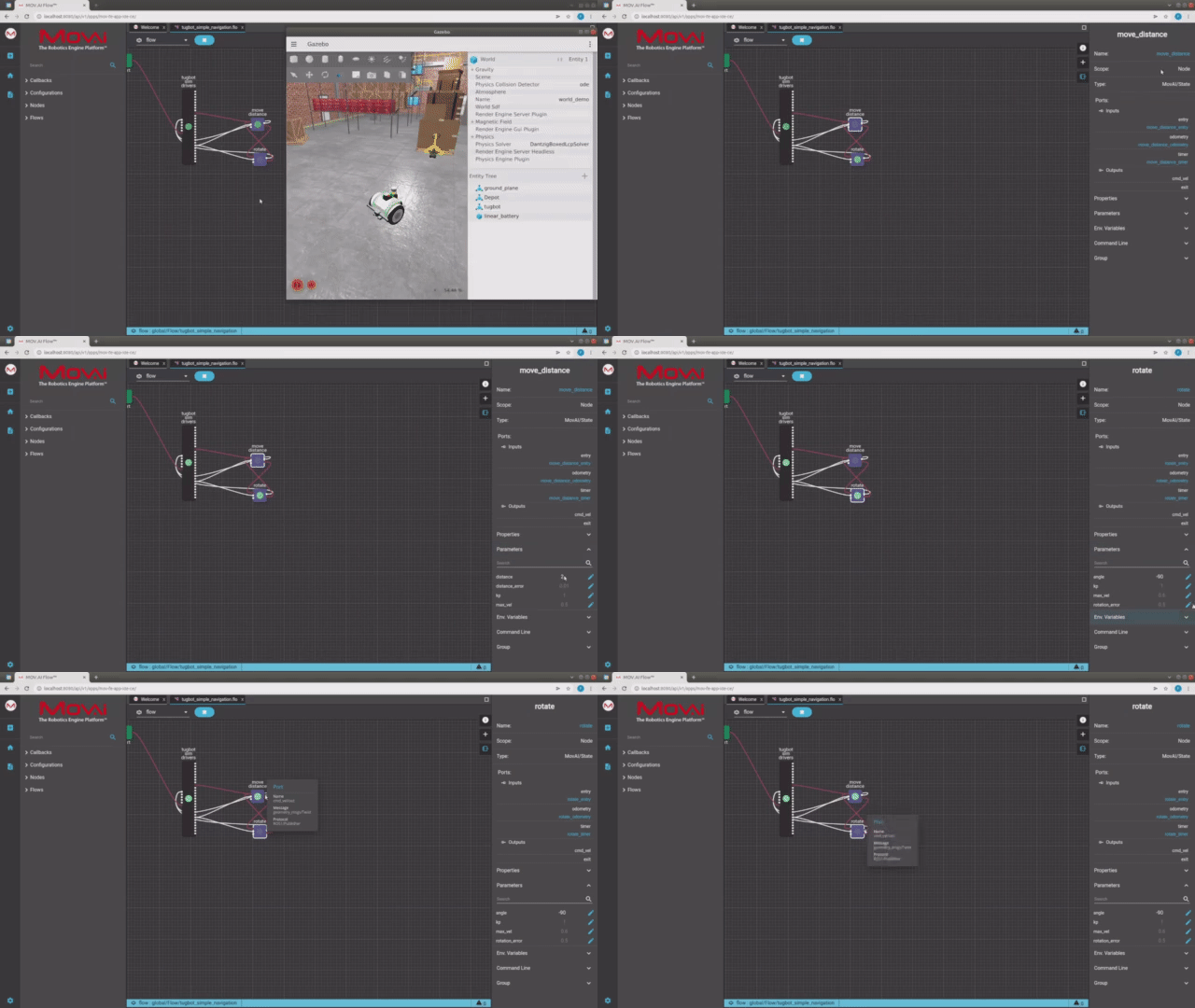
Here's a small taste. Click below to see the full video.
 Watch the steps!
To configure the robot’s behavior –
-
Click on the
 button on the top right of the flow diagram to expand the properties pane of this flow on the right.
 -
Click on the move distance node to display its properties in the right pane, as shown below –
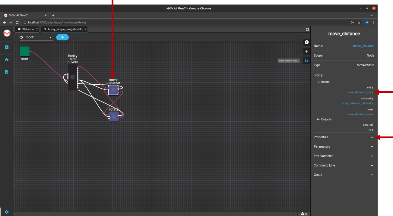
- Click on Parameters
 to expand it to show all the customizable parameters provided for this node. For example, as shown below –
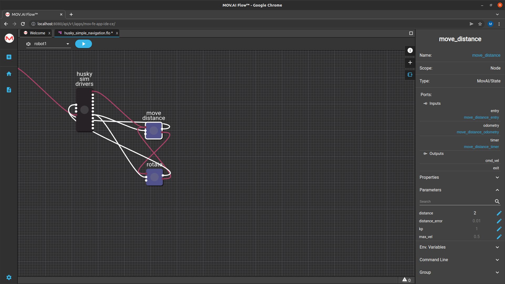
This example shows that currently the value of the distance property is 2, meaning that the robot will travel 2 m.
- To modify this distance, click the Edit
 button next to the distance property to display the following –
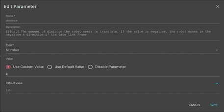
This window describes the purpose of this property. For example, the description above reads –

- This page also enables you to modify the configured distance value.
To do so –
-
Make sure that the Use Custom Valueoption is selected.
-
Change the number in the Value field to specify the distance that you would like the robot to travel (for example, 1 m) and then click SAVE.
The next time you click the Play  button, the robot will travel 1 m in each direction of the square.
MOV.AI saves you the trouble of having to find the required parameter in a yaml file or some other type of large configuration file.
You can also click on any of the display parameters, such as kp, to see the description of what it does and to modify its value.
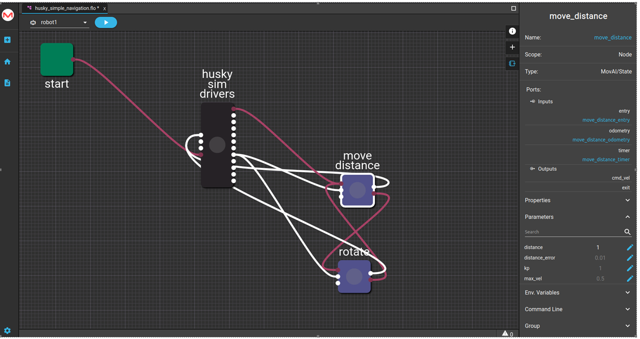
Default parameter values that were defined in the node template appear grayed out. Parameter values that have been edited (such as distance, as described above) appear white. For example, as shown below –
Updated 9 months ago
