Nodes – Autonomous Navigation Application Example
The top part of the autonomous navigation flow has two of the same nodes as were described in A Robot Learning about its Environment, meaning – husky Sim drivers and ekf_odom.
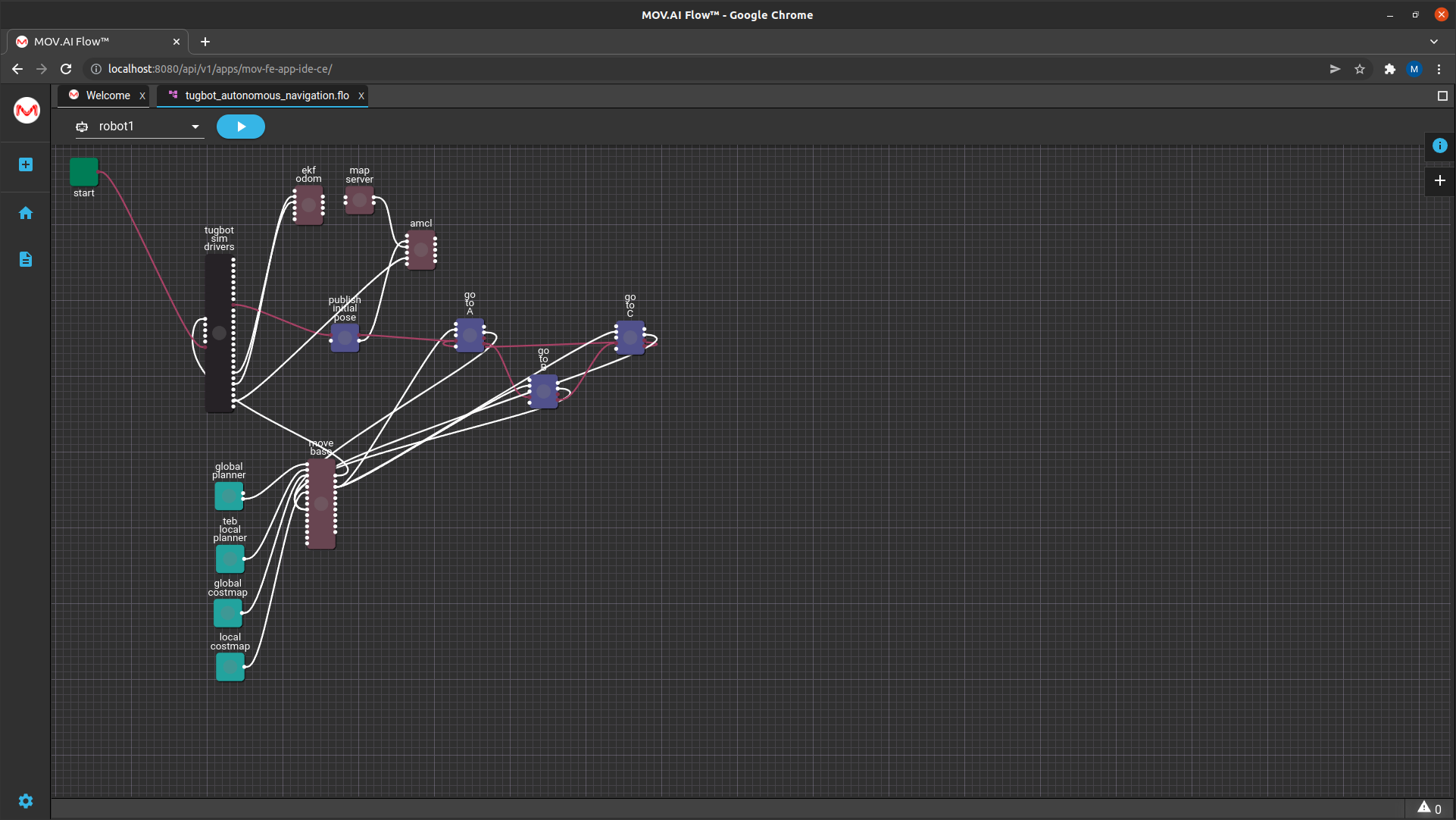
The following sections describes the additional nodes that appear in this flow.
Robot Localization Nodes
The ekf odom, map server, amcl and publish initial pose nodes comprise the robot’s localization functions, as follows –
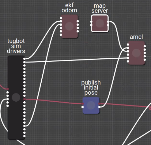
map server
The map_server node retrieves the image map file (map/depot/yaml) to be used in this flow and converts it into a costmap.

This costmap is an internal representation of the image map that represents the cost (difficulty) of a robot traversing various areas of a map. These values help a route planning algorithm find the most efficient routes across the ground and are used by the other nodes in this flow. This costmap divides the ground up into areas that it can navigate (displayed white), areas that it cannot navigate (displayed black) and unknown areas (olive green).
amcl

Robot localization and navigation is inherently inaccurate because of drifting, as described in Learning About Robot Localization.
MOV.AI solves this problem by using the amcl node to verify the location of the robot (using it sensors in real time) and to correct the representation of its location as necessary by providing the system with the actual location of the robot on the map.
Note – The amcl node does not move the robot, it simply represents its latest calculated location according to the information in the MOV.AI system and the information received from the Ignition Gazebo simulation, which is then reflected in the RViz map.
Th amcl node uses the following types of information and tries to match the LiDAR sensor’s laser scan on top of the costmap in order to correct the errors coming from the robot’s odometry and thus to know the real location of the robot –
- The robot’s LiDAR sensor output, which provides a flat (2D) layer of a 3D world at a specific height in the environment, as provided by the robot’s laser scan of the environment. This information is received from the husky sim driver.
– AND –
- The costmap created by the map server node. An output port of the map server node is connected to the amcl node.
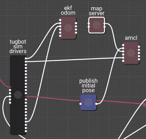
Publish Initial Pose

The initial position of the robot is a parameter of this node – Orientation is [0,0,0,0] and Position is [0,0,0]. Its output port connects to the amcl node in order to tell it where the robot is starting from. Once the amcl node knows its initial position, it can perform position corrections from there as it moves around. See initial_pose_publisher for more information.
Global and Local Planner Nodes
Now that the robot localization nodes (described above) indicate the robot’s precise current position, the following nodes can do their job of executing the velocity commands of the robot starting from that initial position on the map.
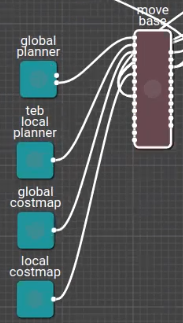
Move base

The move_base node controls the movement of the robot by specifying the velocity commands sent to the robot. The velocity command specifies the linear speed and rotational speed.
The linear speed is forward when the speed is a positive value, and backwards when it is negative.
The rotational direction is determined by whether the rotational speed is negative or positive.
Plug-Ins
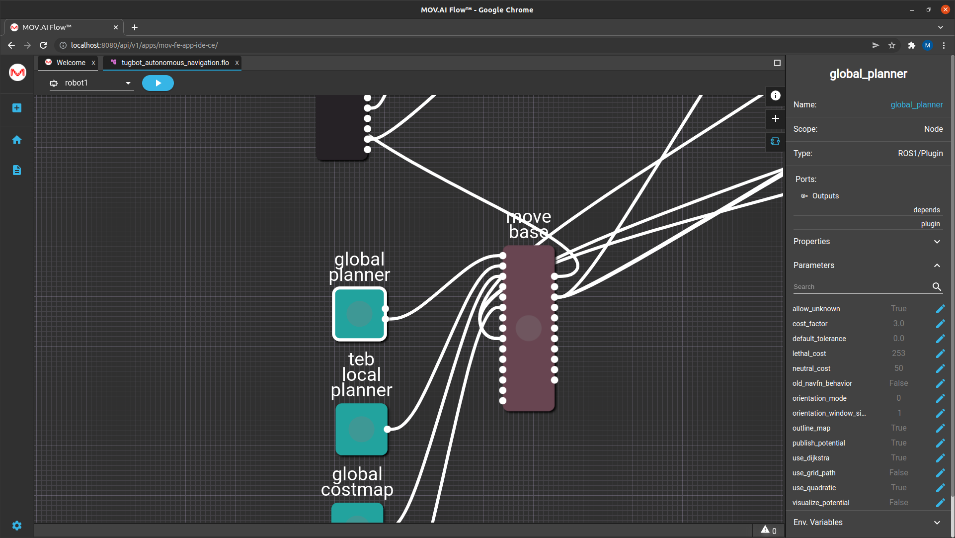
Four ROS plug-ins appear in this flow that represent a set of parameters that can customize the move base node.

The MOV.AI Flow interface visualizes them and enables you to easily customize them.
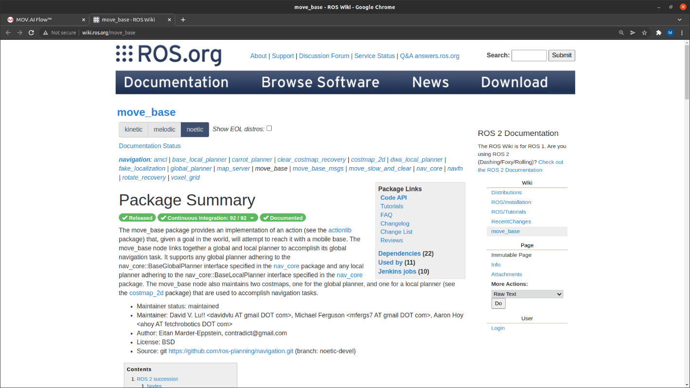
Each of these plug-ins is described in http://wiki.ros.org. For example, you can Google move_base and read about it here http://wiki.ros.org/move_base –
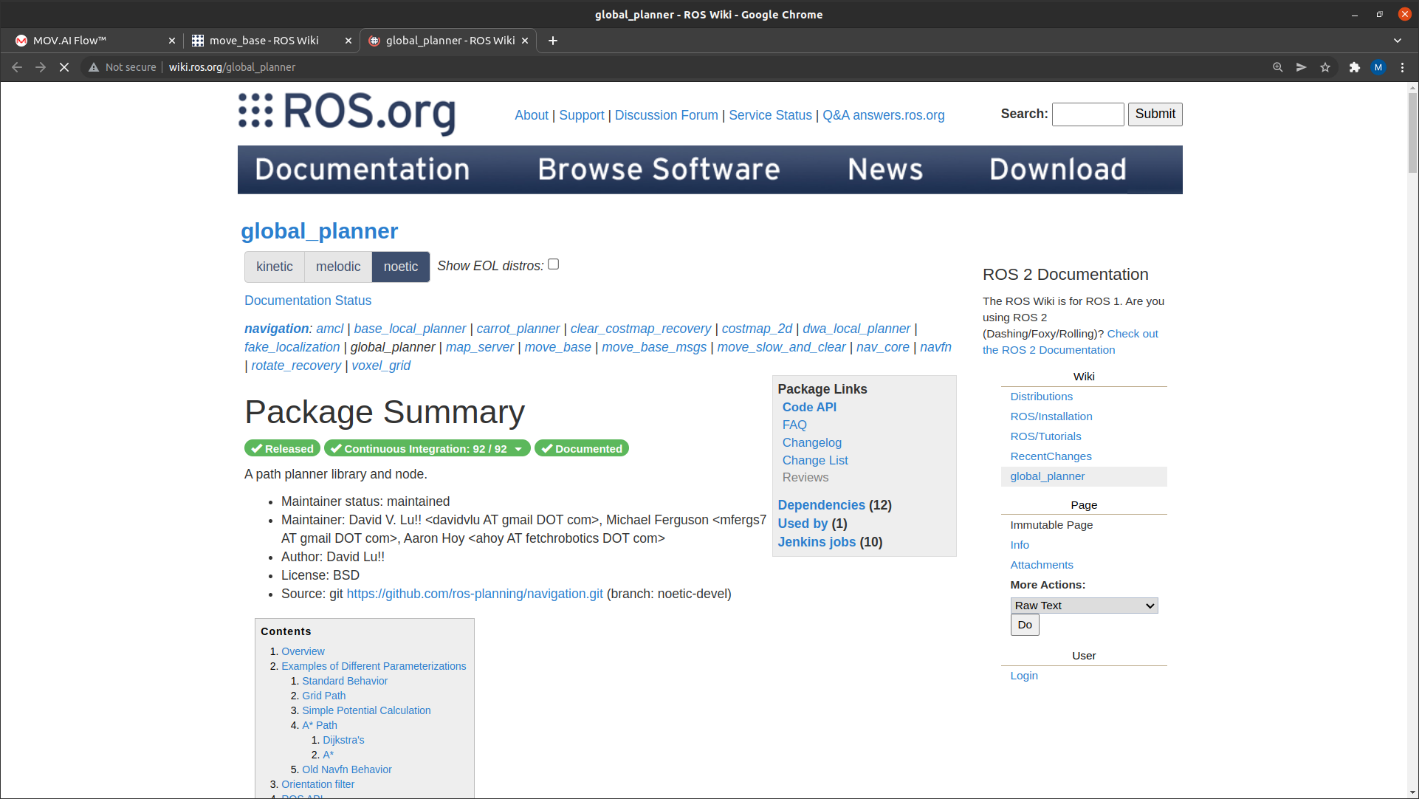
You can also Google wiki ros global planner to read about it here – http://wiki.ros.org/global_planner.
Here is a short overview of these four ROS plug-ins –
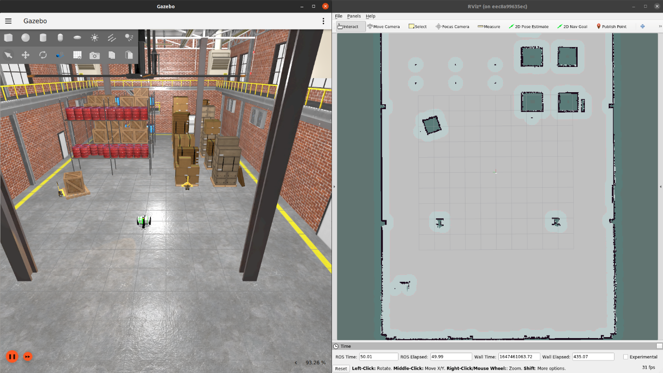
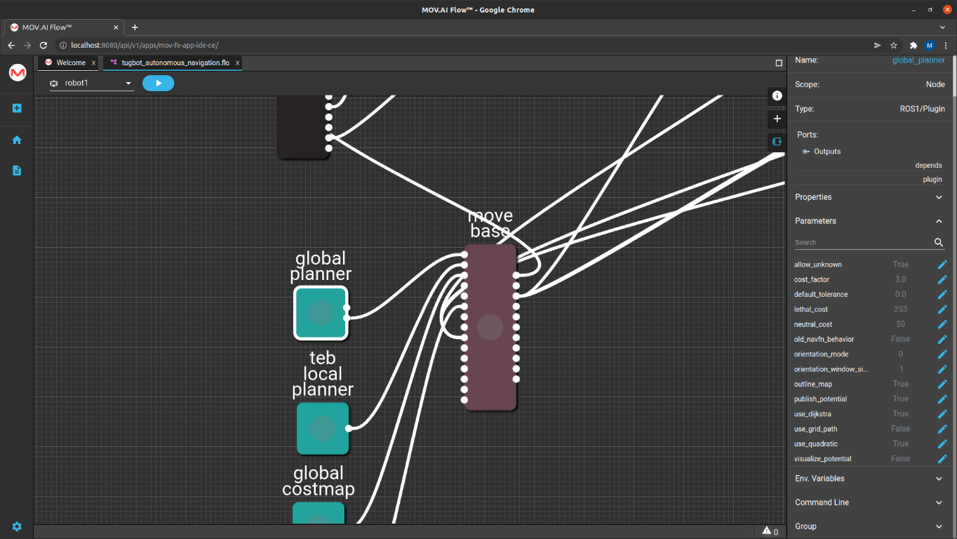
- global planner – The global_planner plug-in helps the move_base node plan a trajectory in the map. For example, if the robot is initially positioned between the pillars on the map and the flow receives an instruction to go to a point at the end of the map. This node is aware of the areas on the map and therefore it can autonomously travel from its initial position to its target destination. The robot is free to plan its trajectory because it is aware of the areas where it can travel (white) and where it cannot because of obstacles (black outside rim/green inside).
Clicking on the global planner node displays a variety of configuration options in the pane on the right.
Note – This is called a free trajectory, which means that the system autonomously plans its route from one point to another.
- global costmap – The global planner node (described above) works with the global_costmap node to help the move base node control the movement of the robot.
- teb local planner – The teb_local_planner plug-in helps the move base node dynamically change the robot’s route while it travels along the trajectory from A to point B. It considers the feedback from the robot’s LiDAR sensor as it travels along its trajectory in order to dynamically handle unexpected obstacles along the way, such as people walking by. This plug-in dynamically plans the robot’s path within a small area in front of the robot as it travels along the route determined by the global planner.
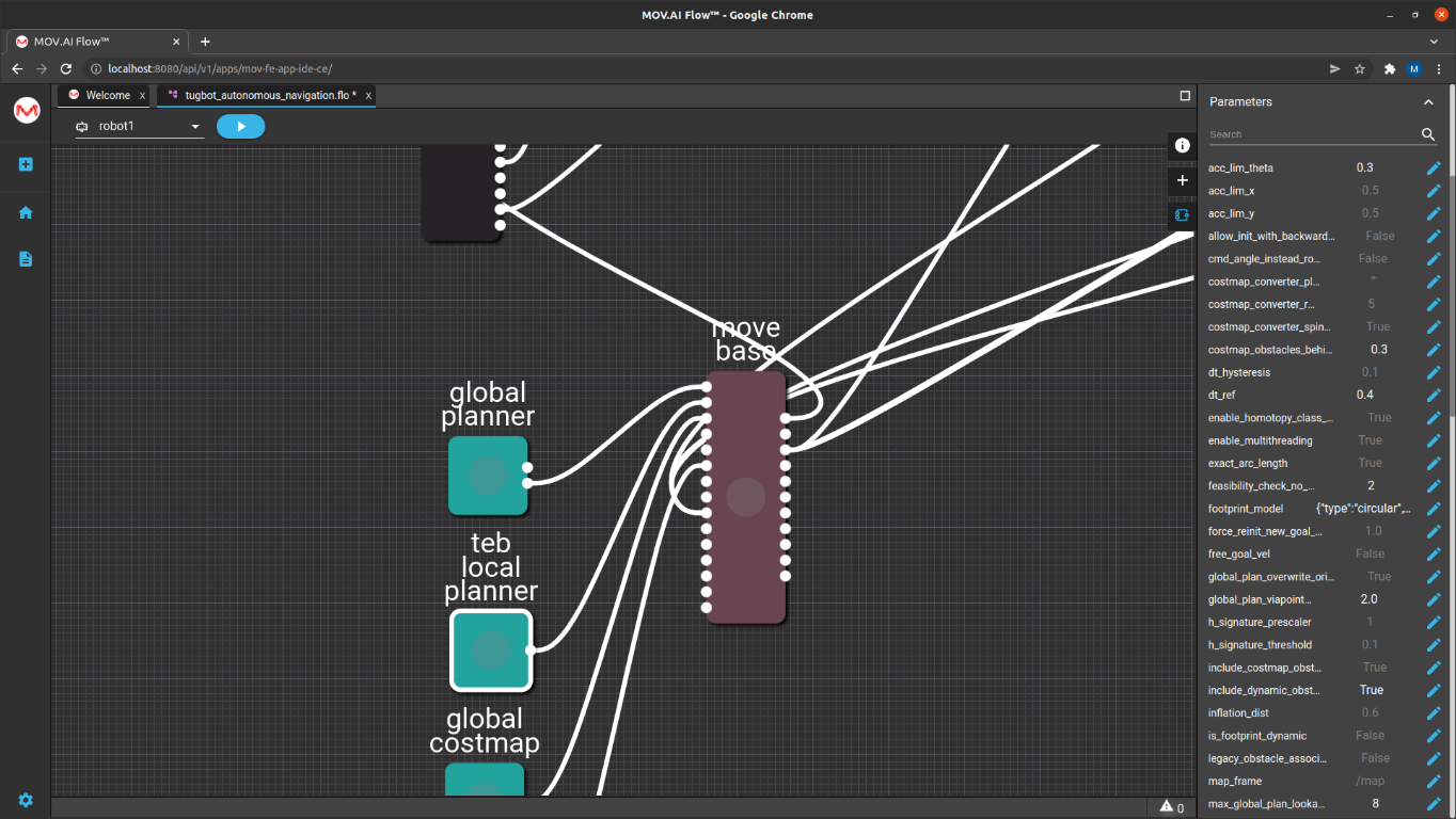
For example, the footprint_model parameter enables you to specify how wide the robot model is. All these parameters are described in ROS, but their description can easily be viewed in MOV.AI by clicking the Edit ![]() button to display the description and editing options of each of the parameters that can be configured. For example, as shown below –
button to display the description and editing options of each of the parameters that can be configured. For example, as shown below –
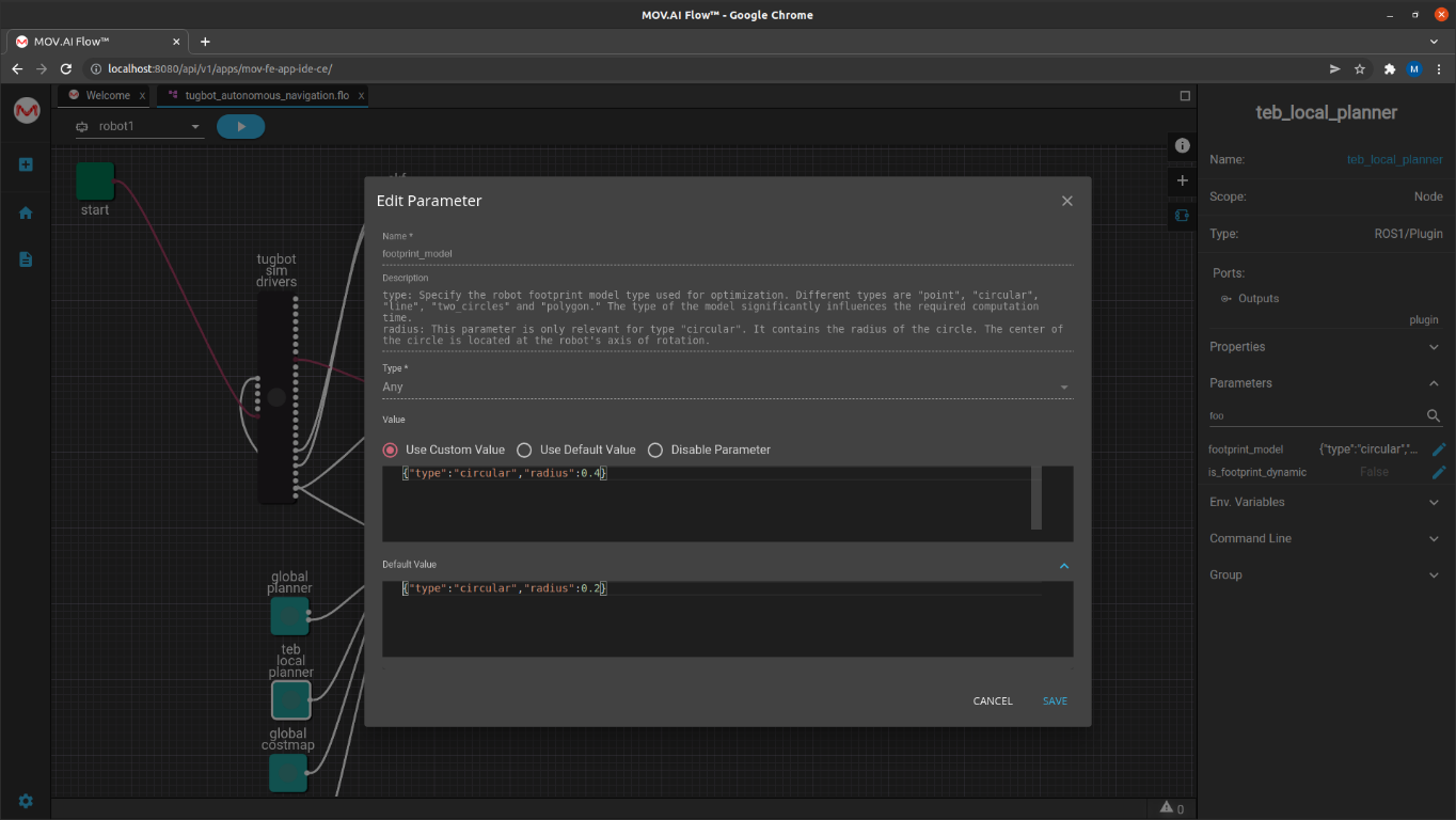
The fact that MOV.AI enables you configure and read the associated descriptions of each parameter of a ROS node is one of MOV.AI’s extremely helpful features.
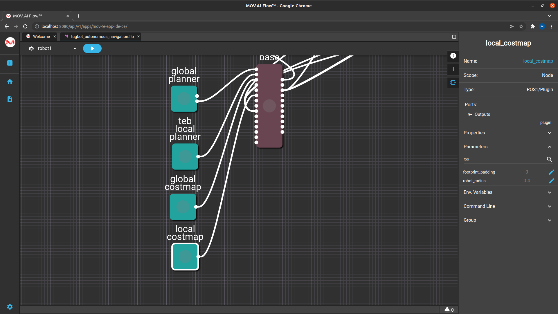
- local costmap – The local planner node (described above) works with the local_costmap node to help the move_base node dynamically plan the robot’s local (nearby upcoming) movement.
Go To Nodes
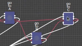
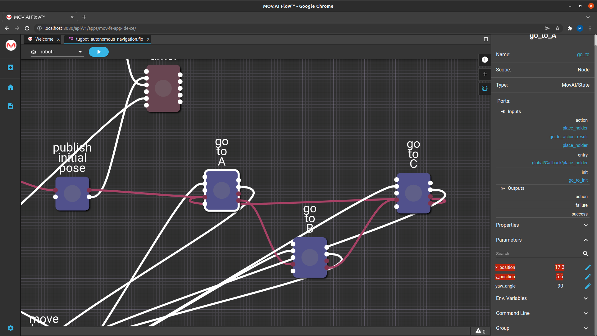
The autonomous navigation node flow has three go_to nodes – go to A, go to B and go to C. Each go to node sends a command to the robot to autonomously navigate to a specific position on the map.
Clicking on one of these nodes and then expanding the Parameters area in the right pane shows three parameters that define a specific position on the map –
- X_postion
- Y_position
- Yaw_angle
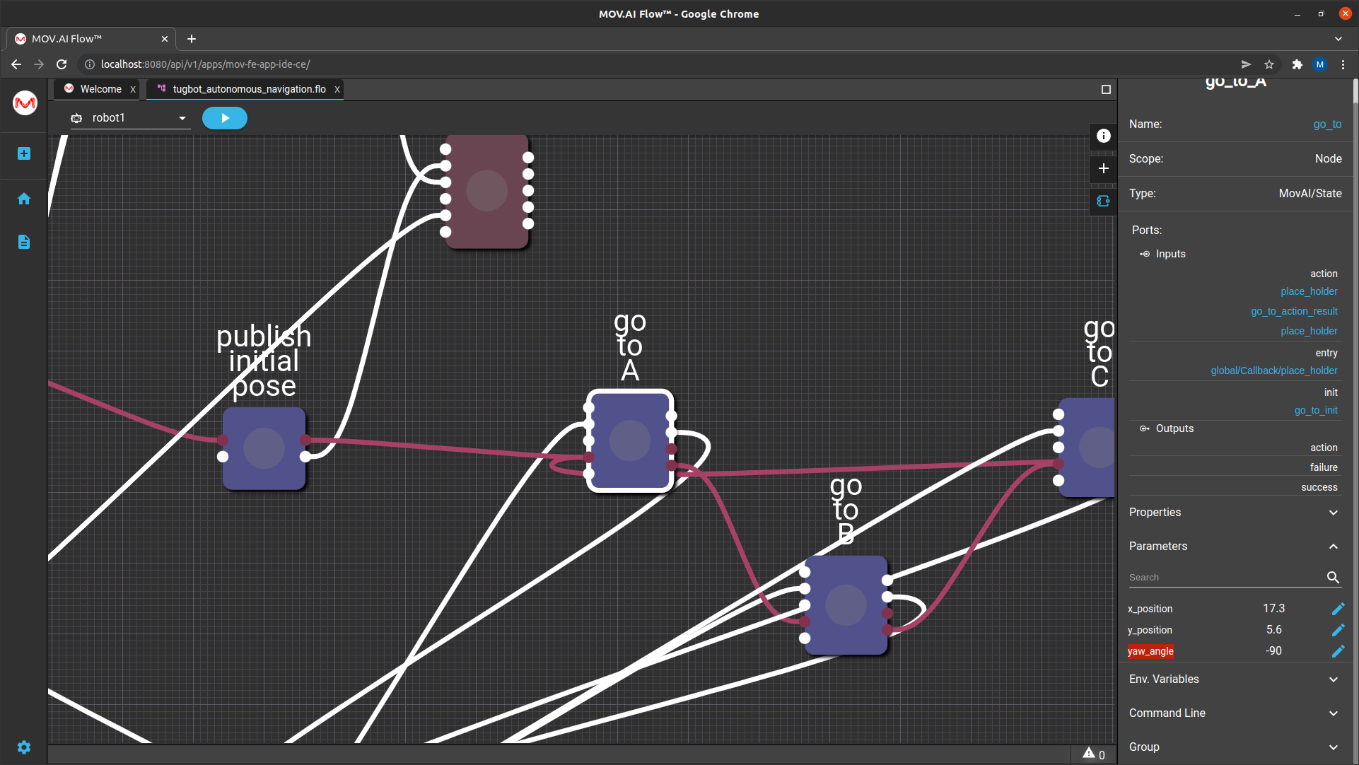
In the flow diagram (shown above), we see that the output port (on the right) of the go to A node is connected to the input port of the go to B node, the output port of the go to B node is connected to the input port of the go to C node; and the output port of the go to C node is connected to the input port of the go to A node.
Therefore, the robot will travel from point A, to point B, to point C and back to point A repeatedly.
To see a specific position on the map –
- Open the map in RViz using the Visualize Map flow, as described in Visualizing the Saved Map.
- Select the husky autonomous navigation checkbox, as shown below –
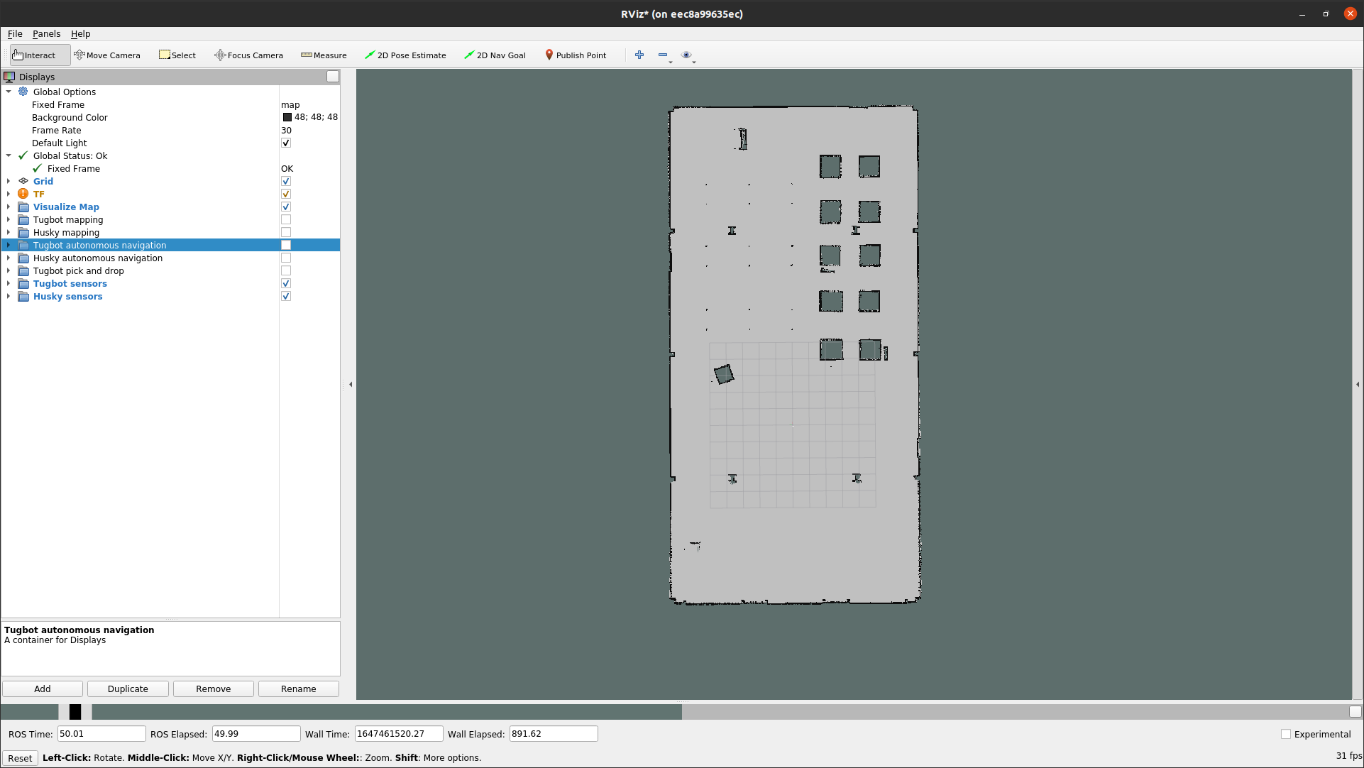
- In RViz, click the Publish Point button in the top right corner.
- You can now hover over any position on the map to display the exact coordinates of this point.
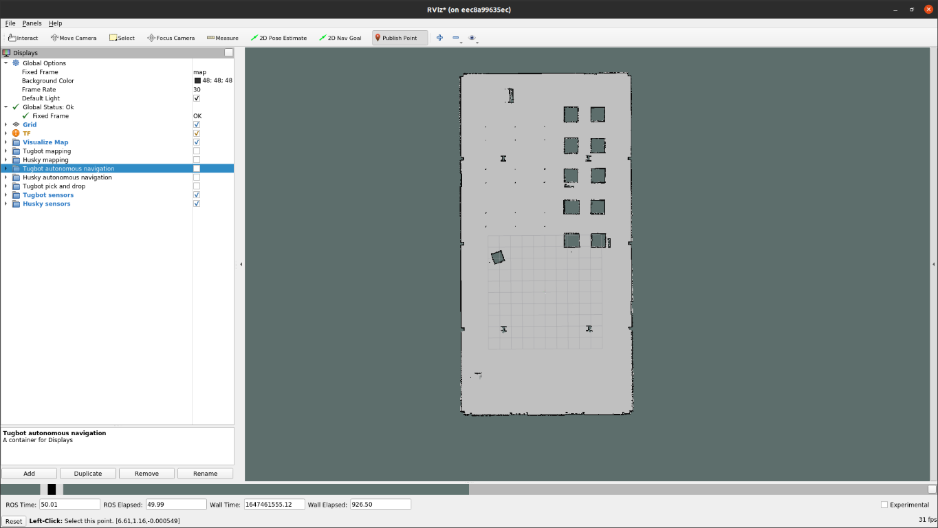
For example, the bottom of the window above shows the following X and Y positions on the map – 
The X coordinates appear on the left followed by the Y coordinate. The example above shows X = 17.2 and Y = 5.3.
Therefore, the value of the x_position parameter should be 17.2 and the y_position parameter should be 5.3, which is almost what is shown below –
The Yaw angle is based on the map’s origin, which specifies the starting angle position of the robot on the map when we started to create the original map.
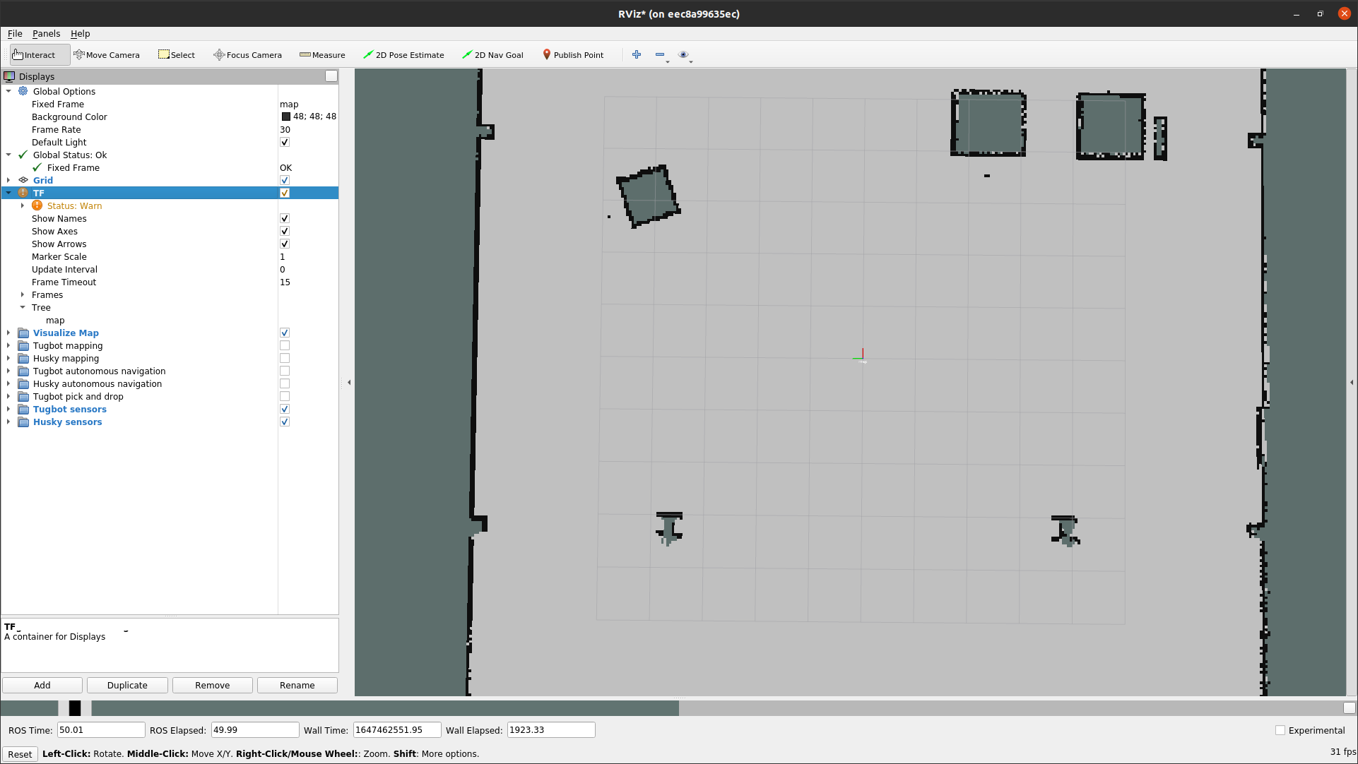
For example, if we started to create the map from the center of the grid shown below and if the front of the robot was facing towards the top of the map, then yaw = 0.
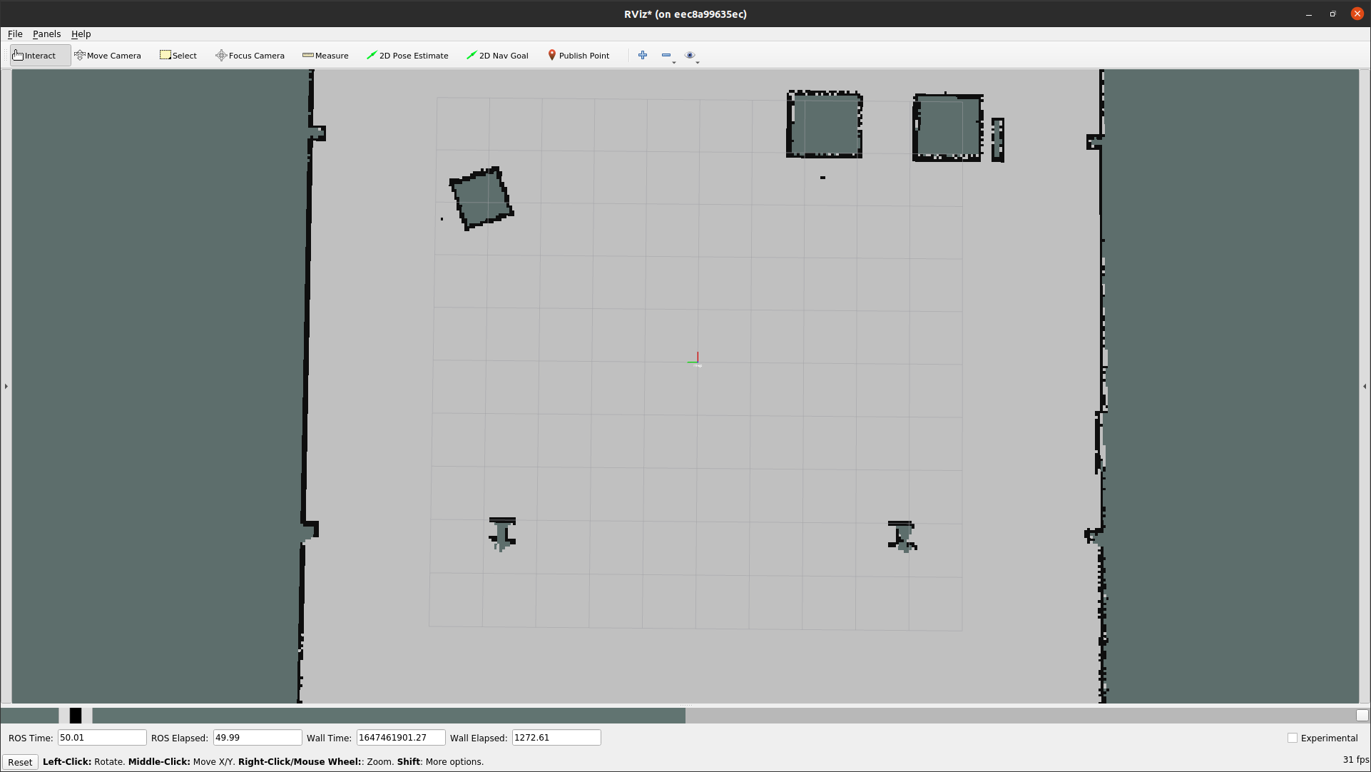
Yaw is the angle of the robot in respect to the map. More specifically it’s the angle of the robot relative to the map when it starts traveling – compared with – the angle of the robot relative to the map when it started creating the map.
Whichever direction the robot is facing when it starts creating the map is considered yaw = 0. Therefore, if the robot is facing the same direction when it gets a navigation command, then yaw = 0 also.
For example, if when the robot starts navigating autonomously, it is facing 90° to the right compared to its original direction when it started creating a map, then the yaw is -90 (this is based on a right hand coordinate system); and if the robot is facing 90° to the left when it starts navigating autonomously compared to its original direction when it started creating a map, then the yaw is +90.
In the image below the map is a perfectly straight and the robot is facing 90° to the right –
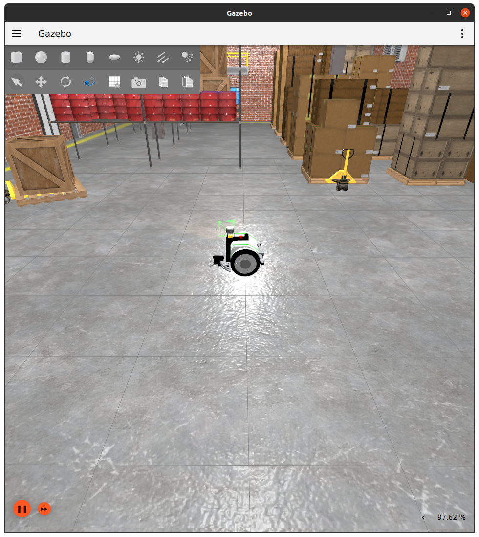
In this example the yaw is set to -90, meaning that the robot will rotate clockwise.
Note – +90 rotates the robot in the counter clockwise direction.
The front of the robot is determined by its base_link frame, which specifies the rotational center of the robot. This is considered to be the center of the robot. The precise position of a robot on the map is actually the precise position of its base_link frame on the map.
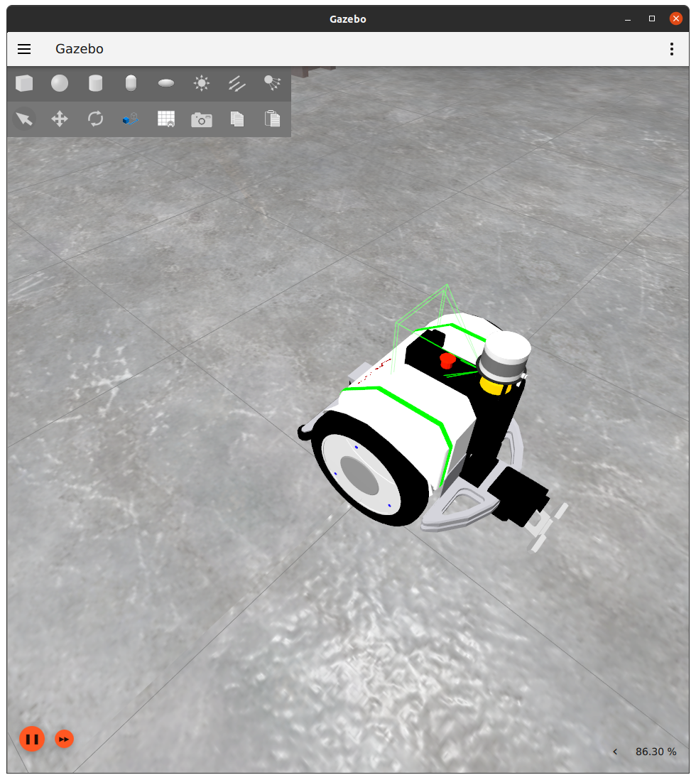
The front of the Tugbot is shown in the picture above, so that movement in the direction of its front, is considered as moving forward.
The robot’s back has a gripper on it so that when the robot moves in the direction of his gripper, it is considered as moving backwards.
Note – Each robot has its own transformation, meaning ROS TF, which represents where its front is according to where its motors, joints, cameras and sensors are.
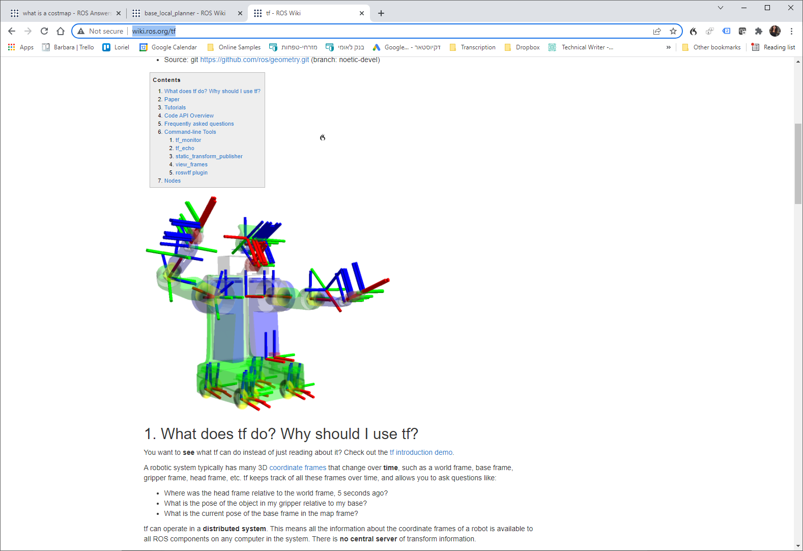
You may refer to http://wiki.ros.org/tf for more information about TF.
Updated 9 months ago
